



What is a slewing ring bearing for crane service? It is a large-diameter bearing that lets the upperworks rotate on the carbody, mast, or pedestal. It carries axial load, radial load, and tilting moment at the same time. The useful engineering question is where that load actually goes inside the ring, and which raceway takes it.
A crane rarely pushes straight down on its bearing. The boom, the hook load, and the counterweight create a large overturning moment, and slewing adds torque and dynamic shock on top. If you only compare diameter and bolt-circle size, you miss the part that decides service life: raceway contact.
How Crane Forces Travel from the Boom to the Foundation
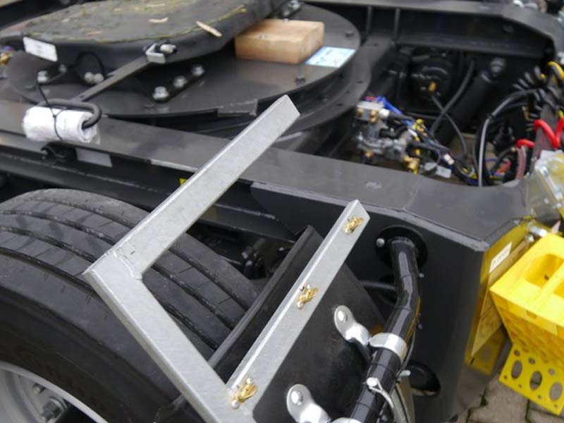
Think of the load as a chain. Every link must be stiff enough to hand the load to the next one without bending away from it. The table below follows a lifting load from the hook to the carbody.
| Stage | What happens to the load | What it means for the bearing |
|---|---|---|
| 1. Boom and hook | Hook weight times radius becomes an overturning moment at the boom foot. | Moment, not weight, usually sizes the bearing. A longer radius raises it fast. |
| 2. Upperworks frame (turret) | The frame turns the boom reaction into a vertical force and a moment couple on the bearing seat. | A flexible frame tilts the ring and concentrates contact at the edges of the seat. |
| 3. Upper mounting interface | Bolts clamp the ring to the frame. Bolt tension on the loaded side rises, and clamp force on the opposite side relaxes. | Bolt preload keeps the ring from separating. Low or uneven preload invites fretting and fatigue. |
| 4. Rolling elements and raceways | The moment splits into a compression zone under the boom side and a lightly loaded zone on the far side. | Only part of the circumference carries peak load. Wear and fatigue start in that arc. |
| 5. Lower mounting interface | The lower ring passes the load into the pedestal or carbody through its own bolts and seat. | Flatness and stiffness of the pedestal control how evenly the raceways share load. |
| 6. Gear mesh (when used) | A pinion or worm drives torque into the ring's teeth for slewing. | Tooth load is separate from raceway load, but ring deflection shifts the mesh. |
The key point is that the loaded arc is not the full circle. Under a moment, the rolling elements on one side carry most of the force while those on the other side may carry almost none. That is why average-load thinking understates raceway stress.
Raceway and Rolling Element Choices Compared
The raceway layout decides how the bearing resists moment. Each design handles combined loads differently, and each has limits. Here is how the main families compare in crane work.
| Bearing type | How it carries combined load | Fits best | Limits |
|---|---|---|---|
| Single Row Slewing Ring Ball Bearings | One ball set in a four-point contact raceway takes axial, radial, and moment load together. | Light to medium crane duty with compact space. | Fewer contact points. Less margin for large moments or shock. |
| Double Row Ball Slewing Ring Bearing | Two ball rows share axial and moment load, with more contact area than a single row. | Medium to heavy crane duty where axial load dominates. | Radial capacity is modest. Needs a wider section than a single row. |
| Crossed Roller Slewing Bearings | Rollers alternate orientation in one raceway. Line contact adds stiffness. | Precision rotation with moderate loads. | Sensitive to mounting flatness. Not the usual choice for the heaviest cranes. |
| Three-row Roller Slewing Bearings | Separate roller rows carry axial load, reverse axial load, and radial load, so each raceway has one job. | Heavy cranes with large moments, such as port and large mobile cranes. | Larger envelope and higher cost. Needs very stiff, flat mounting structures. |
More rows are not automatically better. A three-row roller design has the highest capacity in a given diameter, but a flexible frame can waste that advantage by loading one roller edge. For a small truck-mounted crane, a well-supported single or double row ball design may be the more sensible match.
If your crane is a mobile unit, the Truck Crane Slewing Bearing range is a useful starting reference. For very heavy duty, see our Heavy load slewing bearing options.
Request Your Custom Slew Drive or Bearing Spec
Tell us your load, speed, and environment — receive a tailored 100–5000 mm slewing drive or slewing bearing proposal with 3D drawings within 24 hours.
How Mounting, Clearance, and Gearing Change Raceway Contact
Catalog capacity assumes good installation. Several conditions can move the real contact pattern away from the ideal one. Each item below has a consequence and a trade-off.
- Mounting structure stiffness. A stiff frame and pedestal keep the ring round and flat. A flexible one lets the ring tilt, which concentrates load at raceway edges. Stiffening adds weight and fabrication cost, so match it to the moment you actually have.
- Bolt preload. Correct preload keeps the joint clamped on the tension side. Too little causes loosening and fretting. Too much can overstress bolts or distort the ring seat. Follow the tightening sequence and torque, and check them after initial operation.
- Internal clearance or preload. Tight setups raise stiffness but add friction and heat. Looser setups run freely but tilt more under moment. Cranes that need smooth fine positioning and cranes that take shock loads may need different settings.
- Raceway hardening and material. Raceway surface hardness resists contact fatigue. We select between alloy steel and forged alloy steel by load, speed, and environment. Harder is not always better, because hardening depth and core toughness have to balance.
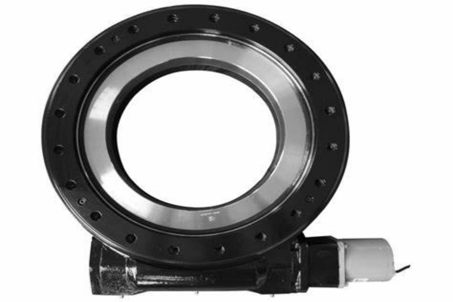
- Gear teeth and drive. A ring with an external or internal gear adds a separate tooth load path. If the ring deflects, the mesh shifts and tooth contact worsens. Integrated drives help here, as the bearing and gearing are designed together. See our Slew Drive range for that approach.
- Sealing and environment. Contamination attacks raceways first. Marine and port cranes need sealing and corrosion protection matched to salt exposure.
These factors interact. A stiff pedestal does little if bolt preload is uneven, and a well-hardened raceway still suffers if the frame tilts the ring. Treat the bearing, bolts, and structure as one system.
Common Misreadings of Load Ratings and Raceway Contact
Most selection problems come from reading a rating chart without its conditions. These are the errors we see most often in specification reviews.
- Comparing capacity curves from different sources. Static and dynamic curves depend on the safety factor, the standard used, and the duty class. Two curves are only comparable if their conditions match.
- Checking axial load only. Hook weight alone says little. Overturning moment, radial thrust from slewing and wind, and shock factors all matter.
- Assuming a larger diameter fixes everything. A larger ring spreads moment better, but only if the frame can support it flatly.
- Ignoring the unloaded side. The far side of the ring can unload under high moment. The bolts there must still hold the joint.
- Treating drive torque as a bearing problem. Starting torque, friction, and brake behavior come from the bearing, seals, and gearing together.
Verification is where numbers become evidence. Ask the supplier for the items below, and note what each one proves.
- Load case table: axial, radial, and moment values with the duty class and safety factor used.
- Raceway hardness and depth records: shows the heat treatment actually applied to the batch.
- Dimensional inspection report: flatness, roundness, and bolt-hole positions. Our bearings go through CMM three-coordinate inspection and dynamic load testing, covered on our Slew Drive Quality Control page.
- Mounting and bolt instructions: grade, torque, and tightening sequence.
- Quality system and warranty terms: we operate under an ISO 9001:2015 quality management system and offer a 2-year extended warranty.
None of these documents replaces a full structural check of your own frame. They show whether the bearing is built to its stated rating, not whether your pedestal can support it.
Worked Example: Reading a Truck-Mounted Crane Slew Assembly
Consider a loader crane on a truck. The boom reaches out to the side, the hook load creates a moment, and the load zone in the bearing sits under the boom foot. When the crane slews to the opposite side, that loaded arc moves around the ring.
A Netherlands material handling equipment manufacturer used 50 units of the WEA9-62-25HR worm gear slew drive on truck-mounted loader cranes. In that application, the integrated drive combines the bearing and the worm gearing in one sealed housing. The ring, gear mesh, and mounting interface were designed as a unit instead of three separate parts.
Marine duty adds a corrosion and shock dimension. UK Ocean Marine Systems took 20 units of the WEA17-104-25H-R-REV.D for shipboard cranes, and a South Korean port equipment maker placed a 20-unit repeat order of WEA9-62-25HR units for port cranes. These cases show the drive format working in lifting equipment. They do not set a rating for your own crane, which still needs its own load case.
For a stand-alone slewing ring bearing for crane duty, or for a drive with a special envelope, Customized Slew Drive engineering is available. Our standard MOQ is 1 set and our customized MOQ is 5 sets. To start, send the following:
- Maximum lifting capacity and boom radius range
- Axial, radial, and moment loads, plus duty class
- Mounting diameters, bolt pattern, and available section height
- Operating environment: marine, port, mining, or road
- Required slewing speed and positioning precision
With those inputs, our engineering team can return a technical proposal within 24 hours, and technical questions get a response within 48 hours. Sample orders are welcome for testing and evaluation before a larger commitment.
Request Your Custom Slew Drive or Bearing Spec
Tell us your load, speed, and environment — receive a tailored 100–5000 mm slewing drive or slewing bearing proposal with 3D drawings within 24 hours.
 WhatsApp

 +8613903880726