


Slew Drive Load Capacity Analysis
What is a Slew Drive?
A slew drive, also known as a slewing drive or slewing reducer, is a compact gearbox mechanism engineered to manage slow-speed rotational movement while simultaneously supporting heavy loads. This integrated device serves as the rotational core of equipment ranging from solar trackers and cranes to aerial work platforms and wind turbines, where both load support and controlled motion are essential. By converting high-speed input power into high-torque output rotation, slew drives enable precise positioning and smooth operation of heavy machinery across numerous industrial applications.
How Does a Slew Drive Work?
Power Input Stage
A slew drive begins its operation by receiving input power from an external source, typically a hydraulic motor, electric motor, or manual hand crank. This input power is characterized by high rotational speed but relatively low torque, which is not yet suitable for directly moving heavy equipment.
Speed Reduction and Torque Amplification
The input shaft transfers this power to a worm gear (in worm gear designs) or a pinion gear (in spur gear designs). As the worm or pinion rotates, it engages with the gear teeth cut into the slewing ring. The significant difference in size and tooth count between the worm/pinion and the large slewing ring creates a substantial gear reduction ratio. This reduction is what transforms the high-speed, low-torque input into low-speed, high-torque output rotation at the slewing ring.
Rotational Output
The slewing ring, now driven by the worm or pinion gear, begins to rotate. Because the equipment—such as a crane boom, solar panel array, or platform—is bolted directly to the rotating ring, it moves in unison. The rotation speed is slow and controlled, allowing for precise positioning of heavy loads.
Self-Locking Mechanism
One of the most valuable features of worm gear slew drives occurs during the power-off state. Due to the geometry and friction angle of the worm and gear interface, the drive becomes self-locking. This means that when the input power stops, the worm shaft prevents the slewing ring from back-driving or rotating under load. No external brakes or holding mechanisms are required, providing inherent safety and stability for applications where maintaining position is critical.
What Is Slew Drive Load Capacity?
Slew drive load capacity refers to the maximum forces and moments a slew drive can safely withstand during operation and when stationary. It represents the structural and mechanical limits of the unit—exceed these limits, and you risk premature failure, unsafe operation, or catastrophic damage.
Understanding load capacity isn't simply about looking at a single number. A slew drive must simultaneously handle multiple forces acting in different directions. The rated capacity is determined through engineering analysis that considers gear strength, bearing raceway geometry, material properties, and safety factors.
Manufacturers provide load capacity curves that visually represent the safe operating zone for combined loads. These curves are essential tools for proper selection—the application's combined load must fall below the limit curve to ensure reliable performance.
Key Types and Features of Loads for Slew Drives
Understanding the three primary load types is essential because every application imposes some combination of these forces on the slew drive. Each load type behaves differently and stresses different components within the drive.
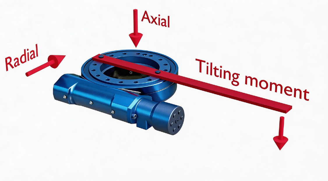
Axial Load (Fa)
Axial load refers to forces that act parallel to the rotation axis—essentially, thrust forces that push along the centerline of the drive.
Direction and Behavior: Axial load can be either downward (compressive) pressing the drive together, or upward (tensile) trying to pull it apart. In most applications, axial load is primarily generated by the weight of the equipment being supported.
Where It Acts: This load is transmitted directly through the bearing raceways and rolling elements. The bearing's raceway angle—typically 45 degrees in four-point contact ball bearings—is specifically designed to handle this thrust efficiently.
Why It Matters: Excessive axial load can cause raceway brinelling (permanent indentation), increased friction, and accelerated wear. The load capacity charts specify maximum allowable axial loads under both static and dynamic conditions.
Radial Load (Fr)
Radial load acts perpendicular to the rotation axis—side loads that try to push the drive sideways or deflect it off-center.
Direction and Behavior: Unlike axial load which aligns with the shaft, radial load comes from the side. Imagine pushing against a vertical pole—that sideways force is radial load.
Common Sources: Wind pressure on tall structures, belt or chain tension in driven systems, and off-center loading all create radial forces. Even gear meshing forces themselves generate some radial component.
Load Distribution: Radial load is carried by only a portion of the bearing raceway at any given moment, concentrating stress on specific rolling elements. This makes proper raceway geometry and material hardness particularly important for radial capacity.
Moment Load (Mk)
Moment load, also called tilting moment or overturning moment, is the most complex and often the most critical load type for slew drives. It represents the bending force that tries to tip the drive over.
How It's Created: Moment load occurs when a force is applied at a distance from the rotation center. The formula is simple but powerful: Moment = Force × Distance. A small force applied far from the center creates the same moment as a large force applied close to the center.
Real-World Example: Consider a crane with a 10-meter boom. A 1-ton load at the boom tip creates a 10 ton-meter moment load on the slew drive at the base. The drive must resist this tipping force through its bearings and mounting structure.
Why It's Critical: Moment load creates a force couple—it pushes down on one side of the bearing while pulling up on the opposite side. This opposing action stresses the entire drive structure, including raceways, rolling elements, and mounting bolts. In most mobile equipment applications like excavators and aerial lifts, moment load is the dominant design consideration.
How They Interact
These three loads never act in isolation. A solar tracker experiences panel weight (axial), wind pressure (radial), and the combination creates complex moments as wind pushes against panels offset from the rotation center. Understanding this interaction is why load capacity curves plot combinations of axial and moment loads—the safe capacity for one decreases as the other increases.
Factors That Influence Slew Drive Load Capacity
Load capacity is not a fixed number—it depends on multiple design, material, and application factors that determine how much force the drive can safely handle.
Design and Geometry Factors
Raceway Design: The internal geometry of the bearing raceway fundamentally determines load distribution. Four-point contact ball bearings, standard in most slew drives, use a Gothic arch raceway profile that provides point contact at four locations. This design allows a single bearing to handle axial, radial, and moment loads simultaneously. The contact angle—typically 45 degrees—optimizes load sharing between axial and radial directions.
Rolling Element Configuration: Single-row ball bearings suit standard loads, while double-row ball bearings or crossed roller designs provide higher capacity. Larger ball diameters increase load capacity but may reduce rotational smoothness. The number of rolling elements also matters—more balls distribute load better but require larger raceways.
Gear Tooth Optimization: Gear teeth must transmit torque while withstanding bending and contact stresses. Designs following AGMA Class 10-12 standards ensure proper tooth profiles, pressure angles, and root fillets that minimize stress concentrations. Helical gears offer smoother engagement than spur gears but generate axial thrust loads that must be considered in overall drive design.
Housing and Mounting Structure: The external housing must be rigid enough to maintain proper gear alignment under load. Deflection in the mounting structure translates directly into misalignment, concentrating stress on small portions of the gear teeth or raceway.
Material Selection and Heat Treatment
Bearing Quality Steels: High-quality materials like 42CrMo, 50Mn, or 4140 steel for slewing rings provide the strength and toughness needed for heavy loads. These alloys offer excellent fatigue resistance and can be heat-treated to achieve required hardness.
Case-Hardened Gears: Gear teeth typically use carburized steels like 20CrMnTi or 8620. Case hardening creates a hard, wear-resistant surface (58-62 HRC) while maintaining a tough, ductile core that resists tooth breakage under shock loads.
Induction Hardening: Raceways undergo induction hardening to create a deep, wear-resistant layer that resists brinelling from rolling element contact. The hardness pattern must be carefully controlled to avoid brittleness while providing adequate surface durability.
Through Hardening vs. Surface Hardening: The choice depends on load type. Through-hardened components resist bulk deformation but may be more brittle. Surface-hardened components maintain toughness internally while resisting surface fatigue.
Lubrication and Operating Conditions
Lubricant Type and Viscosity: Grease or oil must maintain a protective film between rolling elements and raceways under all operating conditions. Higher loads require higher viscosity lubricants or EP (extreme pressure) additives that prevent metal-to-metal contact. Synthetic lubricants offer better performance across wider temperature ranges.
Relubrication Frequency: Proper lubrication intervals are critical. Inadequate lubrication allows metal contact, generating heat and wear that rapidly reduces effective load capacity. The rule of thumb: more frequent lubrication extends life. Operating temperature, duty cycle, and contamination risk all affect required frequency.
Temperature Effects: High temperatures degrade lubricant performance and can soften bearing materials. Low temperatures increase lubricant viscosity, reducing flow and potentially starving contacts. Special lubricants and materials may be needed for extreme environments.
Contamination Protection
Seal Effectiveness: Seals protect the raceway from contaminants that would otherwise act as abrasives, grinding away material and dramatically reducing load capacity. Double-lip seals with metal skeletons provide the best protection for demanding applications.
Environmental Enclosures: For outdoor or dirty environments, enclosed drives with IP ratings prevent particle ingress. Marine applications require additional protection against saltwater corrosion, often through specialized coatings and stainless steel components.
Ingress Prevention During Operation: Even with good seals, operating practices matter. Washing equipment with high-pressure water can force contaminants past seals. Regular inspection of seal condition prevents gradual capacity loss from contamination.
Installation and Maintenance Quality
Mounting Surface Flatness: The mounting surface must be flat within manufacturer specifications—typically 0.1mm or better. Uneven surfaces distort the bearing raceway, creating high spots that concentrate load and reduce effective capacity.
Bolt Torque and Pattern: Bolts must be tightened to specified torque values in a diagonal pattern. Uneven or incorrect torque creates preload variations that alter load distribution. Loose bolts allow movement that can fret and damage mounting interfaces.
Initial Alignment: Proper alignment between the slew drive and driven equipment ensures loads are transmitted as designed. Misalignment introduces unintended radial or moment loads that reduce available capacity for intended forces.
Ongoing Maintenance: Regular inspection, relubrication, and seal replacement preserve load capacity over time. Neglected maintenance allows gradual deterioration—what begins as adequate capacity can become dangerously insufficient as wear accumulates.
Applications of Different Load Types in Practical Use
Understanding how different loads appear in real applications helps you identify what your slew drive will actually experience:
Axial Load-Dominated Applications: Wind turbine yaw systems face primarily axial loads from the massive weight of the nacelle and rotor assembly. The slew drive must support this weight while precisely orienting the turbine to face the wind. Similarly, large radar antenna bases support the antenna's weight while enabling rotational scanning.
Radial Load-Dominated Applications: Belt-driven rotary tables and positioning systems experience significant radial loads from belt tension. The side pull from the belt tries to deflect the rotation axis, requiring the slew drive's bearings to resist this lateral force. Crane guide wheels also encounter substantial radial loading.
Moment Load-Dominated Applications: This is where slew drives face their toughest challenges. Excavators and cranes experience enormous moment loads as their booms extend outward. The force at the bucket or hook, multiplied by the boom length, creates a powerful tipping moment that the slew drive at the machine's base must resist. Aerial work platforms and man lifts face similar demands—as the platform extends upward and outward, the moment load increases dramatically.
Complex Combined Load Applications: Solar tracking systems face a sophisticated combination of loads. Panel weight creates axial load, wind creates both radial loads and complex moments depending on wind direction and panel angle. Industrial robot joints experience constantly varying combinations of all three loads as the arm moves through its work envelope. Marine cranes on ships add another dimension—wave action creates dynamic, unpredictable loading patterns.
How to Choose the Correct Load Capacity for Your Application
Selecting the right slew drive requires a systematic approach:
Step 1: Calculate Your Loads: Determine the maximum forces your application will generate. Calculate axial load from component weights, radial loads from external forces like wind or belt tension, and most importantly, calculate the moment load using M = F × d, where d is the distance from the rotation center to the point of force application.
Step 2: Apply Safety Factors: Real-world operation includes shock loads, wind gusts, and unexpected conditions. Multiply your calculated loads by an appropriate safety factor—typically 1.5 to 2.0, depending on the application's criticality and operating environment.
Step 3: Consult Load Capacity Curves: Every properly engineered slew drive comes with load capacity curves showing the safe operating envelope for combined loads. Plot your adjusted loads on these curves—the point must fall below the limit line.
Step 4: Consider Dynamic vs. Static Ratings: Static capacity is the absolute maximum before structural damage occurs. Dynamic capacity considers fatigue life over time—typically rated for a specific number of rotations or hours of operation. Your application's duty cycle determines which rating matters more.
Step 5: Verify Environmental Compatibility: Ensure the drive's sealing, lubrication, and materials match your operating environment—outdoor, marine, dusty, or extreme temperatures.
LyraDrive: Get Slew Drive 3D Drawing for Your Application
LyraDrive is a professional manufacturer specializing in high-quality slew drives and slewing bearings. With extensive experience in the industry, we understand that every application has unique requirements—there is no one-size-fits-all solution.
Our product range includes multiple types to meet diverse customer needs, including worm gear slew drives, double worm slew drives, and spur gear slew drives. Whether your application demands high torque density, enhanced load distribution, or faster rotation speeds, we have a solution engineered to deliver.
We believe that proper selection starts with accurate information. That's why LyraDrive offers a valuable service to our customers: we provide 3D drawings tailored to your specific application. When you share your load data, mounting requirements, and operating conditions, our engineering team analyzes the information and generates a detailed 3D model of the appropriate slew drive.
This 3D drawing gives you a clear, intuitive understanding of how the drive will fit into your equipment. You can verify mounting interfaces, check clearance, and simulate integration before any commitment. It's our way of ensuring you have complete confidence in your selection—because seeing the solution in your design is better than imagining it.
Whether you need a standard model or a customized solution, LyraDrive combines engineering expertise with responsive service to help you find the perfect match for your application.
FAQ of Slew Drive Load Capacity
Q: What's the difference between static and dynamic load capacity?
A: Static load capacity is the maximum load a slew drive can withstand without permanent structural damage, typically applicable when the drive is stationary or moves infrequently. Dynamic load capacity considers fatigue life under continuous operation—it's lower than static capacity but includes a rated service life, such as 30,000 hours of operation.
Q: How is moment load calculated?
A: Moment load (M) is calculated by multiplying the force (F) by the perpendicular distance (d) from the rotation center to the point where the force is applied: M = F × d. For example, a 1,000 kg load at the end of a 2-meter boom creates 2,000 kg·m of moment load on the slew drive.
Q: What safety factor should I use?
A: Safety factors typically range from 1.5 to 2.0, but the exact value depends on your application. Applications with shock loads, unpredictable forces, or critical safety requirements need higher safety factors. Solar trackers in windy areas, crane swing drives, and aerial work platforms all benefit from generous safety margins.
Q: Can a slew drive handle all three loads simultaneously?
A: Yes—this is exactly what slew drives are designed to do. The challenge is that these loads interact. A drive might handle high axial load OR high moment load, but the combination of both reduces the safe capacity for each. This is why load capacity curves are essential—they show the safe operating zone for combined loads.
Q: How does lubrication affect load capacity?
A: Proper lubrication is critical. The grease or oil reduces friction between rolling elements and raceways, dissipates heat, and prevents metal-to-metal contact. Insufficient lubrication dramatically reduces effective load capacity and leads to premature failure. Operating temperature and duty cycle determine how often relubrication is needed.
Q: What happens if I exceed the rated load capacity?
A: Exceeding rated capacity risks several failure modes: gear tooth breakage, bearing raceway brinelling (permanent indentation), seal failure, and ultimately catastrophic structural failure. In safety-critical applications like cranes or lifts, this creates serious hazard.
Q: How do I know which gear type—worm or spur—is right for my load requirements?
A: Consider your priorities. Worm gear drives offer self-locking capability and handle high moment loads in compact packages, making them ideal for lifting and holding applications. Spur gear drives provide faster rotation speeds and higher precision with less heat generation, better suited for continuous rotation and automation applications. LyraDrive offers both types and can help you match the right technology to your specific loads.