


Slew Drive Internal Failures: Common Causes and Preventive Measures
What Are Slew Drives?
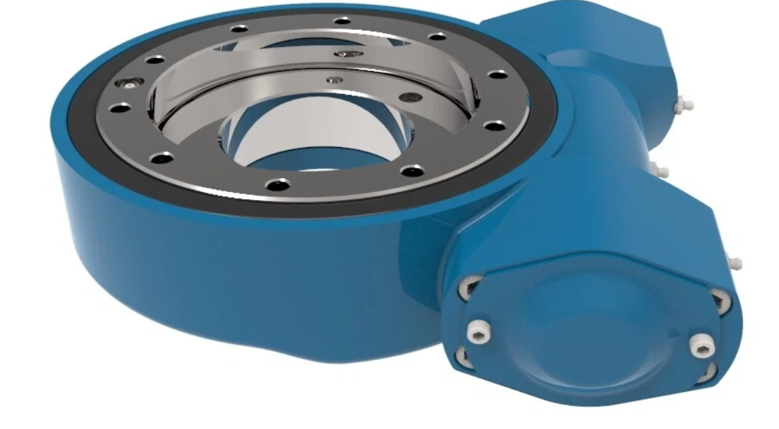
A slew drive is a compact, gearbox-style component engineered to handle heavy loads while enabling smooth, controlled rotational movement. It serves as the core mechanism in applications ranging from construction cranes and aerial lifts to solar trackers and wind turbines. Essentially, a slew drive integrates a slewing bearing—which manages axial, radial, and moment loads—with a drive mechanism into a single, robust unit. This integration allows equipment to rotate precisely under immense stress, making it an indispensable component in modern heavy machinery and industrial automation systems.
How Does a Slew Drive Work?
The operating principle of a slew drive combines simplicity with exceptional effectiveness. A typical slew drive consists of several key components enclosed within a durable housing:
Slewing Ring: A large-diameter bearing that provides the rotational interface and carries all applied loads
Drive Gear: A worm or spur gear that meshes with the gear teeth cut directly into the slewing ring
Housing: A sturdy casing that protects internal components, retains lubrication, and provides mounting points
When an external power source—such as a hydraulic motor, electric motor, or manual crank—turns the input shaft, it rotates the drive gear. This gear's teeth engage with the teeth on the slewing ring, causing the ring to rotate relative to the housing. This gear mesh provides significant torque multiplication and precise control, allowing a small input force to move very large loads with accuracy.
Key Features and Benefits of Slew Drives
Slew drives offer a unique combination of features that deliver significant operational advantages:
High Load Capacity in Compact Form: By integrating a bearing and drive mechanism, slew drives handle substantial axial, radial, and tilting moment loads simultaneously within a space-saving envelope
Self-Locking Capability: Many worm gear slew drives feature natural self-locking, where the friction angle prevents loads from back-driving the motor—providing inherent safety and holding torque without external brakes
Smooth, Precise Positioning: The gear mesh enables fine, controlled movements with minimal backlash, ideal for solar trackers requiring accurate sun-tracking or automation equipment needing exact indexing
Versatility and Durability: Designed for harsh environments, sealed housings and robust bearings withstand shock loads, vibration, and element exposure
Design Flexibility: Multiple configurations and mounting options allow customization for diverse application requirements
The Real Cost of Failure in Slew Drives
When critical equipment relies on a slew drive for primary function, failure never remains an isolated event. It triggers cascading consequences extending far beyond the component itself.
Immediate Safety Hazards represent the most severe cost. A boom lift failing mid-air or a crane losing load control creates potential for injury or loss of life—consequences that can never be fully compensated.
Financial Impact compounds rapidly:
Emergency Repairs and Downtime: Field repairs demand premium labor rates, expedited parts shipping, and extensive troubleshooting. Every unplanned downtime hour for solar farms, port cranes, or production lines translates directly to lost revenue reaching thousands or tens of thousands of dollars
Lost Productivity: Idle equipment represents unrecoverable productivity loss, delaying projects and incurring penalty fees
Secondary Damage: Failing drives often damage surrounding structures, motors, or connected equipment, transforming simple repairs into major overhauls
Long-term Reputation Damage affects both equipment manufacturers and operators. Chronic reliability issues or major safety incidents severely erode customer trust and market standing.
Understanding and preventing slew drive failure root causes is therefore not merely a maintenance task—it is a core business priority ensuring safety, profitability, and reliability.
Common Failure Modes Explained
The majority of slew drive failures are not random events but predictable outcomes of specific root causes. Understanding these five primary failure modes provides the foundation for effective prevention.
Failure Mode #1: Misalignment and Installation Errors
Misalignment represents the most common and most preventable cause of premature slew drive failure. Slew drives are precision assemblies with tight internal tolerances, and incorrect installation distorts these relationships from initial startup.
The Damage Mechanism: When mounting surfaces lack flatness or rigidity, they introduce runout. As the drive rotates, this creates cyclic bending loads on bearing raceways, concentrating stress far beyond design limits. Angular misalignment of the input shaft or driven structure forces improper gear tooth meshing, concentrating load on tooth edges rather than distributing it across full faces. This leads to rapid edge wear, pitting, and potential tooth breakage.
Root Causes: Poor installation practices drive this failure mode—mounting surfaces relying on painted or as-welded structures without machining, improper bolt tightening sequences creating uneven clamping, and absence of alignment verification during assembly.
Symptoms: Watch for unusual periodic noises like grinding or rumbling, excessive vibration at rotation frequency, localized heat generation, and uneven wear patterns on gear teeth or bearing raceways.
Failure Mode #2: Contamination Ingress
Contamination acts as the silent killer of slew drives. Abrasive particles, water, and chemicals breaching drive defenses act as grinding paste on precision surfaces, rapidly accelerating wear and corrosion.
The Damage Mechanism: Solid contaminants cause three-body abrasion between gear teeth and in bearing raceways, creating surface irregularities leading to pitting and spalling. Water contamination degrades lubricant film strength, promotes rust and oxidation, and can create acidic corrosion from microbial growth. Chemicals attack and degrade seals and internal materials.
Entry Paths: Contaminants enter through worn dynamic seals, inadequate breather systems drawing dirty air during thermal cycling, gaps at mounting interfaces from missing gaskets, or poor maintenance practices exposing internals to dirty environments.
Symptoms: Lubricant analysis reveals high particle counts, water content, or wear metals. Visual signs include discolored or milky grease, gritty texture, rust on visible internal parts, and performance changes like increased rotational friction or rough operation.
Failure Mode #3: Overload and Shock Loading
Slew drives are designed with specific load ratings, and exceeding these parameters accelerates failure dramatically.
The Damage Mechanism: When applied loads exceed design limits, contact stresses between gear teeth and bearing rolling elements surpass material fatigue strength. This causes subsurface-initiated spalling—tiny cracks forming beneath surfaces that propagate until material flakes away. Shock loads from sudden impacts, swinging loads, or emergency stops create instantaneous stress spikes that can fracture gear teeth or crack bearing raceways directly, without prior warning.
Root Causes: Operation outside design specifications drives this failure mode—lifting loads exceeding rated capacity, equipment modifications adding weight without drive upgrades, high inertia loads without proper acceleration control, or impacts from wind gusts in solar tracking or crane applications.
Symptoms: Sudden changes in operating noise, visible tooth damage or missing gear segments, rough rotation indicating bearing raceway damage, and complete drive lock-up from debris jamming gear meshes.
Failure Mode #4: Lubrication Failure
Proper lubrication is the lifeblood of any gear drive, and slew drives demand meticulous attention to lubricant type, quantity, and maintenance intervals.
The Damage Mechanism: Insufficient lubrication allows metal-to-metal contact between gear teeth and between rolling elements and raceways. This boundary lubrication condition generates frictional heat, accelerates wear, and can lead to scoring—where localized welding and tearing create rough surface finishes. Incorrect lubricant type fails to form adequate protective films, while degraded lubricant from age or contamination loses its load-carrying additives and viscosity.
Root Causes: Extended maintenance intervals beyond lubricant life, incorrect lubricant selection for operating temperatures or speeds, insufficient fill levels allowing components to run dry, and neglecting regreasing schedules all contribute.
Symptoms: Increased operating temperature, higher torque requirements, unusual noise frequencies indicating metal contact, and lubricant samples showing viscosity breakdown or additive depletion.
Failure Mode #5: Environmental Damage
Slew drives often operate in harsh environments that challenge their material selection and seal systems.
The Damage Mechanism: Extreme temperatures affect lubricant viscosity and seal material flexibility. Temperature cycling creates internal pressure changes that can draw in contaminants through seals acting as one-way valves. Corrosive atmospheres—salt spray in marine applications, chemical exposure in industrial settings—attack unprotected metal surfaces. UV radiation degrades seal materials over time. Ice accumulation can block rotation and damage seals.
Root Causes: Inadequate environmental specification during selection, missing protective coatings, seal materials incompatible with exposure conditions, and lack of environmental protection measures like covers or shields.
Symptoms: External corrosion visible on housing, seal hardening or cracking, lubricant leakage from compromised seals, and intermittent binding from ice or debris accumulation.
Engineering Solutions: How to Prevent Slew Drive Failures
Preventing failures requires proactive, engineering-based approaches addressing each root cause. Implementing these strategies during design, installation, and operation dramatically extends service life.
Solutions for Preventing Misalignment
Design Phase Excellence: Specify tight flatness tolerances for mounting surfaces—typically 0.002-0.005 inches per foot for precision applications. Design mounting structures with sufficient rigidity to prevent deflection under operating loads. Always require machined mounting surfaces for critical interfaces.
Incorporate Alignment Aids: Include pilot diameters that accurately locate drives before bolting. Provide alignment targets or reference surfaces allowing easy installation verification.
Specify and Verify Installation: Document required surface preparation—clean, free of paint or coatings. Specify correct bolt tightening sequences using star patterns and proper torque values. Mandate final alignment verification using dial indicators or laser tools, documenting readings for future reference.
Solutions for Preventing Contamination Ingress
Enhanced Sealing Systems: Select appropriate sealing for operating environments—multi-lip seals, heavy-duty wiper seals, or V-ring seals providing protection against dust and moisture.
Manage Drive Breathing: Equip drives with high-quality, properly sized breather valves or desiccant breathers. These allow air exchange during thermal cycling while filtering contaminants. Inspect and replace breathers regularly to prevent clogging.
Seal All Potential Paths: Always use specified gaskets or O-rings at mounting flanges, never relying on metal-to-metal contact alone. Apply sealant to fastener holes when specified.
Proactive Maintenance: Make regular lubricant analysis a maintenance cornerstone, providing early warning of contamination or wear. When performing maintenance, work in clean environments with clean tools, following strict cleanliness protocols before resealing.
Solutions for Preventing Overload
Proper Specification: Accurately determine all loads—axial, radial, and moment—including dynamic effects like wind loads, acceleration forces, and impact factors. Apply appropriate service factors based on application duty cycles.
Protective Controls: Implement torque limiting devices or current monitoring on drive motors to prevent overload conditions. Include soft-start features for high-inertia loads to control acceleration forces.
Operator Training: Ensure equipment operators understand rated capacities and the consequences of exceeding them. Post clear capacity markings and implement operational procedures preventing overload.
Regular Inspection: Periodically inspect gear teeth and bearings through inspection ports or during maintenance intervals, watching for signs of stress like micro-pitting or crack initiation.
Solutions for Preventing Lubrication Failure
Correct Lubricant Selection: Choose lubricants based on operating temperatures, speeds, and load conditions. Consult manufacturer recommendations for viscosity grade and additive requirements specific to worm gear or spur gear designs.
Establish Maintenance Schedules: Define lubrication intervals based on operating hours rather than calendar time for variable-use equipment. Include both initial fill and regreasing requirements in maintenance documentation.
Monitor Lubricant Condition: Implement regular sampling and analysis programs tracking viscosity, additive levels, and contamination. Establish baseline readings for new drives and track trends over time.
Verify Fill Levels: Ensure proper lubricant quantity during installation and maintenance. Too little fails to protect, while too much can cause overheating and seal damage.
Solutions for Preventing Environmental Damage
Application-Specific Selection: Specify drives with environmental ratings matching actual conditions—marine-grade coatings for salt exposure, stainless steel options for corrosive environments, and appropriate seal materials for temperature extremes.
Additional Protection Measures: Install protective covers or shields in severe environments. Consider auxiliary heating for extremely cold applications to maintain lubricant flow. Apply corrosion-inhibiting coatings to exposed surfaces.
Environmental Monitoring: Include temperature sensors for critical applications to detect overheating before damage occurs. Monitor environmental conditions and adjust maintenance intervals accordingly—more frequent service in dusty or corrosive environments.
Regular External Inspection: Inspect seals, external surfaces, and mounting hardware during routine maintenance. Address minor corrosion or seal degradation before they compromise internal components.
Selecting a High-Performance Slew Drive Manufacturer
Choosing the right partner for slew drive requirements directly impacts equipment performance, reliability, and longevity. LyraDrive brings over 15 years of specialized industry experience to every partnership, delivering engineering excellence and comprehensive support.
Why LyraDrive Represents Your Best Choice:
Decades of Mature Industry Expertise: With approximately 15 years focused exclusively on designing and manufacturing slew drives and slewing bearings, our team possesses deep practical knowledge. We understand real-world challenges from extreme loads in construction to precision tracking in renewable energy.
Engineered for Peak Performance: Our slew drives meet the highest standards through premium materials, precision machining processes, and rigorous quality control. Every drive delivers exceptional load capacity, smooth operation, and extended service life—even in demanding conditions.
Comprehensive Product Range: We offer a complete spectrum of drive types matching specific application needs:
Worm Gear Slew Drives: Ideal for applications requiring high reduction ratios, self-locking capability, and smooth, quiet operation
Spur Gear Slew Drives: Perfect for high-speed, high-efficiency applications where precise positioning and minimal backlash are critical
Double Worm Slew Drives: Providing higher reduction ratios and enhanced self-locking for the most demanding torque and safety requirements
Complete Customer Support: Our responsibility extends beyond product delivery. Every drive includes comprehensive after-sales support and expert technical guidance. Our application engineers ensure correct selection, proper installation, and effective maintenance practices—helping prevent failures and maximize equipment uptime.
LyraDrive: Get Custom Slew Drive 3D Drawings for Your Specific Application
Every application presents unique requirements, and standard solutions sometimes fall short of perfect fit. LyraDrive's custom engineering capabilities transform specific requirements into precision-engineered reality through streamlined, collaborative processes leveraging advanced technology.
Our Customization Process:
Share Your Requirements: Provide key data and specifications including load requirements (axial, radial, moment), rotational speed, desired gear ratio, input type (hydraulic, electric, manual), mounting dimensions, and environmental considerations.
Advanced 3D Analysis and Modeling: Our engineers utilize state-of-the-art 3D design and analysis software to study your application thoroughly. We simulate performance under your specific conditions, ensuring optimal gear meshing, structural integrity, and load distribution before manufacturing begins.
Receive Your Custom 3D Drawing: Based on thorough analysis, we provide detailed custom 3D drawings for review and approval. This allows visualization of the component in your assembly, verification of all interfaces, and confirmation that specifications meet expectations.
Precision Manufacturing and Delivery: Once design finalization, our skilled team begins precision manufacturing. Combining 15 years of experience with advanced production equipment, we deliver custom slew drives that fit perfectly, perform flawlessly, and enhance overall equipment capability.
From robust self-locking worm gear slew drives to high-speed precision spur gear slew drives and exceptional torque capacity double worm slew drives, LyraDrive possesses the expertise to customize the perfect rotational solution.
Technical FAQs: Slew Drive Failure, Prevention, and Solutions
Q1: What is the most common cause of premature slew drive failure?
Misalignment during installation represents the most frequent and preventable root cause. Issues like non-flat mounting surfaces or improper bolt tightening create excessive, uneven loads that rapidly wear bearings and gears.
Q2: How can contamination be detected early?
Regular lubricant analysis provides the most effective early detection. Testing samples reveals high particle counts indicating abrasives, water presence, or elevated specific metal levels signaling accelerated component wear.
Q3: Are all slew drives self-locking?
No. Self-locking primarily characterizes worm gear slew drives, resulting from friction angle between worm and gear preventing load back-driving. Spur gear slew drives typically lack self-locking and may require external brakes to hold position.
Q4: What is the difference between worm gear and spur gear slew drives?
Worm gear slew drives use a worm to turn a gear, offering high reduction ratios, smooth quiet operation, and natural self-locking. Spur gear slew drives use straight pinion gears, providing higher efficiency for increased speeds but lacking self-locking characteristics.
Q5: How do I select the correct lubricant for my slew drive?
Consult manufacturer recommendations based on operating temperature range, duty cycle, and drive type. Worm gear drives typically require specialized gear oils with friction modifiers, while spur gear designs may use standard industrial gear lubricants.
Q6: What maintenance intervals should I follow for optimal service life?
Base intervals on operating hours rather than calendar time for variable-use equipment. Typical schedules include quarterly lubricant analysis, annual seal inspection, and regreasing at manufacturer-specified intervals. Harsh environments demand more frequent attention.
Q7: Can overload damage be detected before catastrophic failure?
Yes. Regular inspection reveals early warning signs including micro-pitting on gear teeth, unusual operating noises, increased vibration, and higher than normal operating temperatures. Implementing load monitoring and torque limiting devices provides continuous protection.
Q8: What information is needed to request a custom slew drive design from LyraDrive?
Provide key application parameters including load requirements (axial, radial, moment loads), rotational speed, desired gear ratio and input torque, mounting space constraints, environmental conditions, and specific interface requirements. Our engineers use this information to create initial 3D models.