


Slew Drive installation Options: Face Mount vs. Flange Mount vs. Shaft Mount
The performance, reliability, and cost-effectiveness of a slewing drive system depend heavily on choosing the right mounting configuration. While engineers often focus on load capacity and gear ratios, the way a slew drive attaches to your machinery fundamentally affects installation complexity, maintenance accessibility, and long-term system durability. This guide explores the three primary mounting options—face mount, flange mount, and shaft mount—to help you make the best choice for your application.
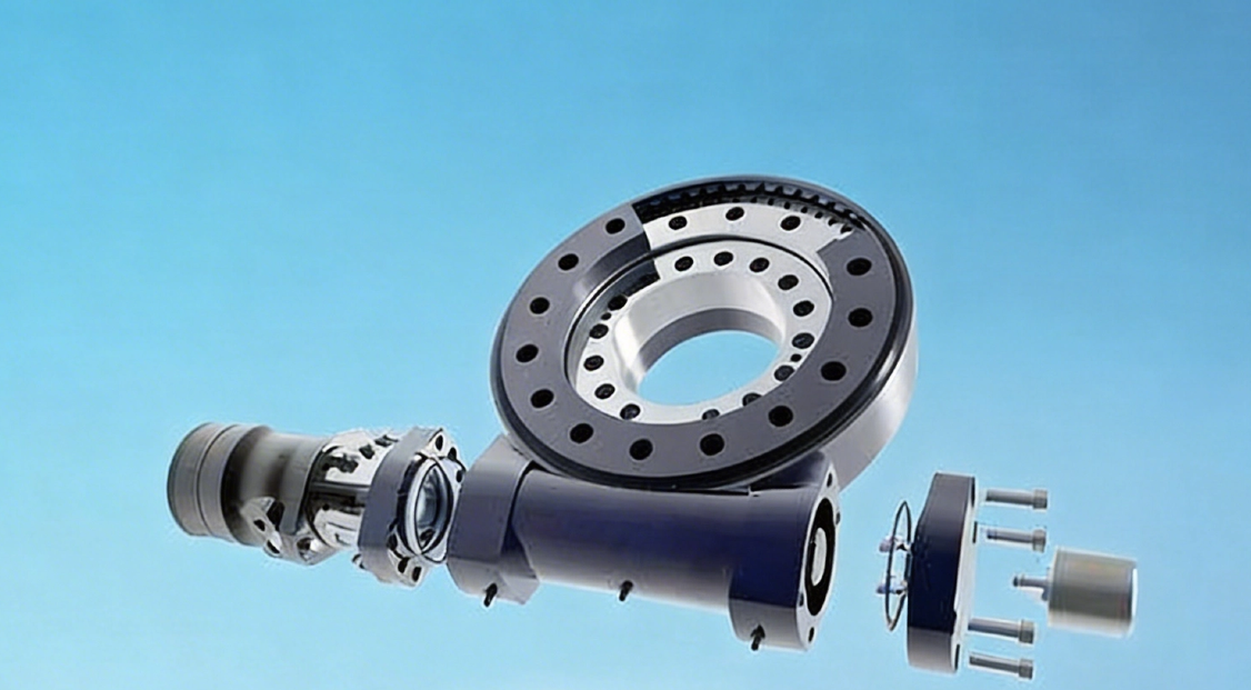
Before we dive into the specifics of each mounting method, it's essential to establish a common understanding of what a slew drive is and how its core components function. This foundational knowledge will make the discussion of mounting interfaces and their design implications much clearer.
What are Slew Drives?
At its simplest, a slew drive is a compact, gear-driven mechanism designed to handle heavy loads while enabling precise, controlled rotational motion. It is essentially a single-unit solution that combines the functions of a bearing and a speed reducer, allowing one structure to rotate smoothly relative to another.
To appreciate how a slew drive achieves this, let's look at the key components that work together inside every unit. Understanding these parts is the first step in grasping why their proper installation is so critical.
Basic Components of Slew Drives
A typical slew drive integrates several key components into one robust assembly:
The Slewing Bearing: The heart of the drive, this large-diameter bearing supports axial, radial, and moment loads.
The Gear Reduction System: Usually a worm gear, spur gear, or planetary set that provides torque multiplication and speed reduction.
The Housing: A protective casing that encases internal parts and, most importantly for our topic, provides the structure and machined surfaces for mounting.
Mounting Interfaces: These are the precisely machined surfaces and bolt patterns on the housing and rotating element that allow for attachment to your equipment.
Seals: Protective elements that keep contaminants out and lubricants in, ensuring long service life.
With these components in mind, you can start to see how they create a powerful and versatile device. The combination of these elements into a single package is what gives slew drives their unique set of advantages.
Key Features and Benefits of Slew Drives
Slew drives are favored for their ability to handle complex, multi-directional loads in a compact form. They offer high precision, excellent holding torque (especially in worm gear designs), and self-locking capabilities in many configurations. Their integrated design simplifies machine building by replacing multiple components with a single, pre-assembled unit, which enhances reliability and reduces overall system cost.
How Does a Slew Drive Work?
The magic of a slew drive lies in how it transfers load and motion. Power is introduced through an input shaft (connected to a hydraulic motor, electric motor, etc.) which rotates the gear—such as a worm or spur pinion. This gear meshes with the teeth on the large slewing ring. As the pinion turns, it drives the rotation of the slewing ring.
Critically, the load transfer occurs through the mounting interface. All external forces from the equipment—whether they are axial thrust, radial loads, or tilting moment loads—are transmitted through the mounting bolts and surfaces into the drive's housing and then directly into the integrated slewing bearing. The mounting configuration dictates the path these forces take, making its proper design essential for bearing life and system rigidity.
The Role of the Installation Method of Slew Drives
The installation method is far more than just a mounting detail; it is a core design decision. The mounting configuration defines:
The Load Path: How forces from your machine flow into and through the drive.
Space Envelope: The physical footprint the drive will occupy in your machine.
Structural Requirements: The design of the mating structures needed to support the drive.
Assembly & Maintenance: The ease with which the drive can be installed, accessed, and serviced.
Choosing the correct configuration from the start prevents performance issues, reduces manufacturing costs, and ensures long-term reliability.
Primary Installation Methods for Slew Drives
There are three primary ways to mount a slew drive, each with distinct mechanical characteristics.
Face Mount
Concept: In a face mount configuration, the stationary housing of the slew drive features a machined flat face, usually on its base. This face bolts directly to your equipment's support structure. The rotating element is the large-diameter slewing ring gear itself, which has its own bolt pattern to attach to the part of your machine that needs to rotate (like a solar panel array or a crane platform).
Advantages:
Extremely Compact Axial Profile: This design is exceptionally thin, making it ideal for applications with severe height restrictions.
High Moment Capacity: The large diameter of the slewing ring provides a wide stance, offering superior resistance to tipping or overturning forces (moment loads).
Efficient Load Distribution: The large bolt circle spreads loads over a broad area, reducing stress concentrations.
Limitations:
Requires Significant Radial Space: It needs ample room in diameter to accommodate the large ring gear and its bolt pattern.
Critical Surface Flatness: The mounting surface on your structure must be extremely flat and rigid to avoid distorting the bearing.
Perimeter Access Needed: Installing and torquing the numerous perimeter bolts can be challenging in tight spaces.
Flange Mount
Concept: This configuration features a housing with an integral flange—a protruding rim with bolt holes—that attaches to your equipment. The flange extends radially from the housing body. The output can be either a rotating ring (smaller in diameter than the flange) or an output shaft.
Advantages:
Balanced Dimensions: It provides a good compromise between axial and radial space, suiting applications with moderate constraints in both directions.
Flexible Output Options: The same housing can often accommodate different output types (ring or shaft).
Robust Mounting: The flange creates a strong, rigid interface that resists deformation and maintains alignment.
Good Adaptability: It can be easily mounted to frames, plates, or custom brackets.
Limitations:
Not Optimal for Extremes: It's not as axially compact as a face mount, nor as radially compact as a shaft mount.
Intermediate Complexity: It represents a middle ground in complexity and cost between the other two types.
Moment Capacity Trade-off: Its bearing diameter (and thus moment capacity) is typically less than a comparable face mount drive.
Shaft Mount
Concept: A shaft mount slew drive has a more cylindrical housing. The stationary part is mounted via a protruding shaft that is clamped into a bore or pillow block on the machine frame. The rotating output is typically a separate shaft or a hub that comes out of the opposite side of the housing.
Advantages:
Radially Compact: It requires minimal space in diameter, making it perfect for installations where side clearance is limited.
Simple Installation: Mounting can be as simple as securing the shaft in a standard bearing support.
Versatile Orientation: The drive can often be mounted in any orientation (horizontal, vertical, etc.) with relative ease.
Easy Motor Integration: The input shaft is often easily accessible for direct coupling to a motor.
Limitations:
Longer Axial Length: It typically has the longest axial footprint of the three types.
Lower Moment Capacity: Because the support is a single shaft, its resistance to moment loads is lower and relies heavily on the rigidity of the mounting structure.
Concentrated Loads: Forces are transferred through the shaft, creating higher localized stresses that must be managed in the equipment design.
| Mounting Method | Key Concept | Primary Advantages | Main Limitations |
|---|---|---|---|
| Face Mount | Stationary housing bolts via a flat face; large-diameter ring gear rotates. |
|
|
| Flange Mount | Housing has an integral flange that bolts to the structure; output can be a ring or shaft. |
|
|
| Shaft Mount | Stationary part is a shaft clamped into a support; rotating output is a separate shaft or hub. |
|
|
Applications for Different Installation Methods
The choice of mounting method is often dictated by the specific demands of the application.
Face Mount Applications
Its compact height and high moment capacity make it the go-to choice for:
Solar Tracking Systems: Where a low profile is essential for wind load management and aesthetics.
Aerial Work Platforms: For rotating the boom or work basket.
Rotating Platforms: Such as those in radar systems, antennae, or small turntables.
Compact Construction Equipment: Like mini-excavators where space is at a premium.
Why Face Mount? These applications share a common need: they must handle significant tipping (moment) forces while operating within tight height restrictions. The face mount's large-diameter bearing provides exceptional resistance to overturning loads, while its ultra-flat profile allows for seamless integration into low-clearance designs. Whether it's a solar tracker fighting wind loads or a mini-excavator working in confined spaces, the face mount delivers the stability and compactness required.
Flange Mount Applications
The balanced nature of flange mounting makes it highly versatile for:
Material Handling Equipment: In conveyor systems and rotary actuators.
Medical Equipment: For precise, controlled movement in scanners or surgical tables.
Industrial Machinery: As a general-purpose rotary positioning element.
Robotics: For joint actuators that require a robust, balanced mounting interface.
Why Flange Mount? What connects these diverse applications is their need for a mounting solution that doesn't compromise on any single dimension. Medical devices demand precision and smoothness; robotic joints require rigidity without bulk; industrial machinery needs versatility. The flange mount's balanced proportions, flexible output options, and robust interface make it the "Goldilocks" choice—not too compact, not too bulky, but just right for applications where adaptability and reliability matter most.
Shaft Mount Applications
The radial compactness of shaft mounts is ideal for:
Automated Machinery: Where drives need to be integrated into crowded production lines.
Packaging Equipment: For applications like rotating labeling stations or filling heads.
Specialized Vehicles: In steering systems or auxiliary drive functions.
Applications with Pillow Block Supports: Where the drive can be mounted between two standard bearing supports.
Why Shaft Mount? These applications are united by one critical constraint: limited side clearance. In crowded production lines or complex vehicle systems, radial space is often the scarcest resource. The shaft mount's slim profile allows it to slip into tight spots where bulkier drives simply won't fit. Its simple installation in standard bearing supports also makes it the preferred choice for applications where ease of integration and maintenance access are top priorities.
Critical Design Considerations for All Installation Types
Regardless of which mounting method you choose, several universal design principles must be followed to ensure success:
Surface Flatness & Rigidity: For face and flange mounts, the mating surface must be flat and rigid. Any deviation can distort the housing and bearing, leading to premature failure. The reference article notes that tolerances are often as tight as 0.010" to 0.030" across the mounting diameter.
Bolt Strength and Preload: Use the correct grade and size of bolts, and tighten them to the specified torque. Proper bolt preload is essential to clamp the drive firmly and prevent movement under load, which can cause fretting and bolt failure.
Alignment: The axis of the drive must be precisely aligned with the rotating structure it will drive. Misalignment creates binding, uneven wear, and excessive parasitic loads on the bearing and gear teeth.
Load Path: Ensure the structure supporting the drive is designed to handle the reaction forces. The load path from the application, through the drive, and into the support structure should be as direct and rigid as possible.
Access for Maintenance: Consider how you will access the drive for inspection, lubrication, or replacement. Will you be able to reach the bolts? Is there enough room for a torque wrench? Planning for this during the design phase saves significant time and effort later.
Conclusion
Choosing the correct mounting configuration—face, flange, or shaft—is a critical step in integrating a slew drive into your machinery. Each method offers unique advantages in terms of space envelope, load handling, and installation complexity, making them suited for different application families. By carefully weighing these factors against your specific requirements, you can ensure optimal performance and long-term reliability.
At LyraDrive, we understand that every application is unique. Our comprehensive product series covers a wide range of drives with all these mounting configurations, from compact face mount designs for solar trackers to robust shaft mount hollow bore drives for automation machinery. Our engineering support team is ready to help you select the best mounting configuration, and we excel at developing custom solutions when standard options don't perfectly match your application requirements.
LyraDrive: Get Custom Slew Drive 3D Drawings for Your Specific Application
Does your project demand a truly unique solution? LyraDrive offers a full range of high-quality slew drives, including worm gear slew drives, spur gear slew drives, and double worm slew drives. We specialize in providing customized products tailored to your exact needs. Simply provide us with your relevant data and design drawings. Our expert engineers will use advanced 3D technology to analyze, model, and develop a precise solution, delivering a custom slew drive drawing and final product that integrates perfectly with your machinery.
FAQs: Installation & Mounting Considerations for Face, Flange, and Shaft Mount Slew Drives
Proper installation is critical to the performance and longevity of any slew drive. Below are frequently asked questions regarding the three primary mounting configurations, addressing common challenges, failure points, and best practices for each type.
General Installation FAQs
Q: What is the most common cause of slew drive failure related to mounting?
A: By far, the most common cause is improper mounting surface preparation. For face and flange mounts, this means inadequate flatness of the mating structure. For shaft mounts, it means poor alignment or insufficient support rigidity. These issues distort the drive housing, leading to bearing misalignment, uneven gear wear, and premature failure.
Q: How important is bolt torque during installation?
A: It is absolutely critical. Bolt preload (achieved by torquing to specification) is what creates the clamping force to securely hold the drive. Insufficient torque allows movement and fretting. Excessive torque can strip threads or distort the housing. Always use a calibrated torque wrench and follow the manufacturer's specifications.
Q: Do I need to use a specific type of bolt?
A: Yes. Always use bolts of the grade, size, and material specified by the slew drive manufacturer. Using inferior or incorrect bolts is a major safety risk and a common cause of mounting failure.
Face Mount FAQs
Q: My mounting structure is a welded fabrication. How can I ensure it's flat enough for a face mount drive?
A: Welded structures almost always require post-weld machining of the mounting surface to achieve the required flatness tolerance (often within 0.010" to 0.030" across the diameter). Do not rely on the as-welded surface. If machining is impossible, a face mount might not be the right choice for your application.
Q: I'm concerned about accessing all the perimeter bolts in my tight design. Any advice?
A: This is a key design consideration. You must design your machine structure to provide tool access to every bolt. This might involve creating access holes, using extended socket wrenches, or designing the surrounding structure to be removable. If access is impossible, consider if a flange or shaft mount drive could be used instead.
Q: What happens if I only tighten some of the bolts on a face mount drive?
A: This would be a critical error. An incomplete bolt pattern will not distribute the moment loads evenly, causing extreme stress concentrations on the few bolts that are installed and on the drive housing itself. This will lead to rapid bolt fatigue failure and potential cracking of the drive.
Flange Mount FAQs
Q: My application has moderate space constraints. How do I verify a flange mount drive will fit?
A: You need to check both the radial clearance for the flange itself and the axial space for the housing and any output shaft or ring. Obtain the detailed 2D or 3D drawings from the manufacturer (like LyraDrive) and perform a virtual fit-up in your CAD model to check for interferences in all positions.
Q: Can a flange mount drive be used in a vertical orientation?
A: Yes, many flange mount drives are perfectly suitable for vertical mounting. However, you must consult the manufacturer. Vertical mounting can affect lubrication distribution and may require special attention to sealing to prevent oil leakage down the output shaft. The drive's specification sheet should indicate if it's approved for all orientations.
Q: The flange on my drive has a spigot or pilot recess. What is its purpose?
A: That pilot feature is crucial for accurate alignment. It mates with a corresponding recess or shoulder machined into your equipment structure, ensuring the drive is perfectly centered. Always utilize this feature; do not rely solely on the bolts for alignment, as bolt clearance holes allow for too much movement.
Shaft Mount FAQs
Q: How do I ensure proper alignment when mounting a shaft mount drive?
A: Precise alignment between the drive's mounting shaft and the support structure (e.g., pillow block bearing) is essential. Use precision shims under the support structure to adjust its height and position until the drive shaft is perfectly level and aligned both horizontally and vertically. A laser alignment tool or a dial indicator is highly recommended for this task.
Q: What is "shaft fretting" and how can I prevent it?
A: Fretting is a wear phenomenon that occurs when there is slight, repetitive motion between the clamped shaft and its mounting bore. This can happen if the clamp force is insufficient. It creates a reddish, dust-like wear debris and can eventually damage the shaft. Prevention is simple: clean the shaft thoroughly, apply a recommended anti-seize compound (if specified), and tighten the clamping bolts to the exact torque specification to prevent any micromovement.
Q: My shaft mount drive will experience high moment (tipping) loads. Is this configuration suitable?
A: A standard shaft mount drive may not be the best choice for high moment loads. Because all the support comes from a single shaft, the structure holding that shaft must be exceptionally rigid to resist the tipping force. For very high moment loads, a face mount drive, which uses a large-diameter bearing, is inherently more suitable. Consult with an engineer to analyze the loads on your specific setup.