



What is slew bearing bolt torque? It is the tightening torque applied to the fasteners that clamp a slewing bearing or slew drive to its mounting structure. The purpose is not simply to make bolts feel tight. The torque creates clamp load, which holds the bearing ring firmly against the mounting faces during rotation, shock loading, and repeated duty cycles.
When technicians find reduced slew bearing bolt torque, rocking, or repeat loosening, the first task is to separate the symptom from the cause. A lower torque reading can result from normal early embedment in a new joint, but it can also indicate settling mounting faces, damaged threads, worn bolt heads, insufficient clamp load, or movement caused by cyclic loading.
Do not treat every torque drop as a failed bearing. At the same time, do not simply retighten every bolt and return the machine to service. A bolt that repeatedly loses tension may be reporting movement elsewhere in the joint.
Start With the Symptom and Establish a Reliable Baseline
The best first action is to document the condition before changing anything. Record which bolts show reduced resistance, whether the issue is limited to one area of the ring, and whether rocking occurs at a certain boom position, turntable angle, or load condition. This helps distinguish a local mounting problem from a wider joint condition.
Torque is an indirect indicator of bolt tension. Friction under the bolt head, in the threads, and at the mounting interface affects the torque reading. For that reason, a bolt can show a different torque response without proving that its clamp load changed by the same amount.
Use the bearing, equipment, or fastener supplier’s approved tightening sequence and torque specification as the reference. Do not substitute a general torque chart when the installed fastener grade, lubrication condition, washer arrangement, thread engagement, or mounting design is unknown. Generic charts are useful only for rough planning, not for confirming an installed slewing joint.
| Initial Check | What to Observe | What It May Indicate | Next Action |
|---|---|---|---|
| Service history | Recent installation, bearing replacement, structural repair, transport, or overload event | A new joint may be settling; a repaired structure may have changed alignment | Compare findings with the original installation and inspection records |
| Location of affected bolts | One bolt, a cluster, one side of the ring, or a full-circle pattern | A cluster often points to a local contact or structural issue; a broad pattern may point to installation or duty-cycle effects | Inspect the related mounting area before retightening |
| Rocking behavior | Movement only under load, at one rotational position, or throughout rotation | May indicate uneven support, local settling, or bearing/internal damage | Stop the diagnosis at the bolt level and inspect the joint and bearing condition |
| Bolt condition | Damaged threads, stretched appearance, corrosion, head marking damage, or washer distortion | The fastener may no longer deliver predictable clamp load | Remove from service as required by the equipment procedure and assess replacement needs |
A single loose fastener after first installation does not automatically mean the bearing is defective. However, a repeat condition after correct tightening deserves closer investigation. This is especially true on excavator turntables, crane bases, forestry attachments, and other equipment exposed to reversing loads.
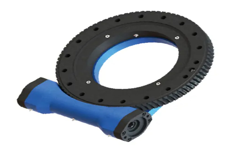
For equipment using a separate rotating drive assembly, inspect the mounting joint of both the bearing and the drive. A Slew Drive can transmit repeated starting and stopping loads into its mounting structure, so the drive bolts and bearing bolts should not be treated as unrelated checks.
Separate Normal Embedment From Settling, Surface Damage, and Cyclic Loosening
The key boundary is whether the torque drop stabilizes after normal joint embedment or continues because the clamped parts are moving. Embedment is the small seating movement that occurs when microscopic high points on bolt heads, washers, threads, paint edges, and mounting surfaces compress under clamp load. It is usually associated with a newly assembled joint that becomes stable after inspection and approved retightening.
Joint settling is different. It occurs when the mounting structure, spacer, washer, paint layer, or unsupported area continues to compress or shift. Surface damage is different again: gouges, raised burrs, corrosion products, weld spatter, or local deformation can prevent full face contact. Cyclic-load-induced loosening occurs when repeated motion reduces effective clamp load and allows the joint to work under service loading.
| Observed Condition | Most Likely Interpretation | Reasoning | Appropriate Boundary |
|---|---|---|---|
| Minor early change after initial assembly, then stable readings and no rocking | Normal embedment may be possible | New contact surfaces can seat under initial clamp load | Proceed only according to the approved retightening and inspection procedure |
| Torque reduction returns after each approved tightening cycle | Joint settling or cyclic movement is more likely | A stable joint should not continue losing effective clamp force without an underlying change | Do not rely on repeated retightening as the repair; inspect faces, bolts, and structure |
| Affected bolts grouped around one sector of the bearing | Local surface damage, uneven support, or localized structural deflection | The pattern is not consistent with uniform whole-joint embedment | Inspect the matching mounting face and surrounding structure |
| Visible rocking, fretting marks, reddish debris, polished contact patches, or paint disturbance | Relative movement at the joint | These signs can appear when clamped components move against each other | Stop normal operation until the mounting condition is assessed |
| Reduced torque with damaged threads, corrosion, distorted washers, or marked bolt heads | Fastener or interface damage | Friction and load transfer are no longer predictable | Escalate for fastener assessment; do not assume retorque restores the original condition |
The conclusion is simple: stable early seating can be acceptable when the installation procedure allows for it and the joint remains firm. Recurrent loss, local patterns, or any visible movement are warning signs. Those conditions do not fit the normal embedment explanation.
This distinction matters on large rotating rings such as Heavy load slewing bearing designs. Their mounting bolts carry the consequences of structural flexibility, moment loads, and repeated working cycles. A bolt check must therefore include the support structure, not just the fastener head.
Request Your Custom Slew Drive or Bearing Spec
Tell us your load, speed, and environment — receive a tailored 100–5000 mm slewing drive or slewing bearing proposal with 3D drawings within 24 hours.
Follow This Diagnostic Order Before Retightening or Replacing Parts
Use a staged inspection. Start with checks that are accessible and non-destructive. Move toward disassembly only when the evidence points beyond a normal tightening issue or when the equipment manufacturer’s procedure requires it.
- Secure the equipment and remove operating load. Park the machine on a stable surface and isolate motion according to site safety rules. Do not check a slewing joint while the structure is carrying a suspended or unstable load.
- Review the installation reference. Confirm the specified bolt type, washer arrangement, tightening pattern, lubricant condition, and inspection interval. If these records are missing, do not guess at an alternative torque value.
- Mark and map the suspect bolts. Identify the affected locations around the ring. A simple position map lets the next inspection determine whether the condition remains in one sector or spreads around the joint.
- Inspect exposed bolt and washer surfaces. Look for corrosion, thread contamination, damaged coatings, contact marks, washer cupping, or evidence that the bolt head has moved. A damaged bolt or washer should not be judged only by its final torque reading.
- Inspect the joint perimeter. Check for gaps, crushed paint, fretting debris, displaced seal material, or uneven contact between the bearing ring and mounting structure. These observations may show that clamping force is being lost through joint movement.
- Check for rocking under a controlled approved inspection method. Observe whether movement is tied to a particular rotational position or loading direction. Rocking in only one area can point toward a local mounting face issue or a bearing condition that needs further diagnosis.
- Compare bolt behavior around the full circle. If only one area changes, inspect that local structure first. If the pattern is widespread, review the installation process, load duty, and fastener preparation across the full joint.
- Escalate before internal bearing work. Raceway inspection, bearing removal, and structural correction should be planned with the equipment and bearing documentation. Do not remove a bearing merely because one bolt showed reduced resistance.
This sequence fits service managers who need to control downtime while avoiding premature replacement. It does not replace the machine manufacturer’s safety procedure, especially on cranes, aerial platforms, mining machinery, and personnel-lifting equipment where a mounting-joint concern may require immediate removal from service.
On a large turntable, for example, a cluster of bolts near one side may show repeat reduction after retightening. If that same sector also has disturbed paint at the joint edge and rocking under a controlled check, the working conclusion is not “use more torque.” The evidence points toward a contact, support, or structural issue that should be inspected before the fasteners are reused.
By contrast, if a newly installed ring shows a small early change with no rocking, no local marks, and stable results after the approved follow-up inspection, normal seating remains a possible explanation. The limit is clear: this conclusion applies only when the joint becomes stable and the installation procedure supports that follow-up action.
Match Corrective Action to the Confirmed Evidence
Retightening is appropriate only when the inspection supports it. If the bolts, threads, washers, mounting faces, and structure appear sound and the supplier’s procedure calls for a follow-up check, use the specified sequence. Cross-pattern tightening helps distribute clamp load around the ring rather than pulling one side down first.
Do not use retightening as a cure for damaged threads, distorted washers, corroded fasteners, or visible joint movement. In those cases, the torque wrench may reach the specified value while the joint still lacks predictable clamp load. The corrective action must address the damaged part or support condition.
| Evidence Found | Recommended Action | Why This Fits | Verification After Action |
|---|---|---|---|
| Stable joint after approved follow-up check, no visible movement | Document the inspection and continue scheduled monitoring | The condition is consistent with seating that has stopped | Confirm later inspections remain stable |
| Dirty, corroded, or damaged threads | Assess replacement using the approved fastener requirement | Thread friction and load transfer cannot be assumed | Inspect mating threads and confirm correct installation condition |
| Washer distortion or bolt-head movement marks | Inspect fastener set and contact surfaces before replacement | These marks may show local movement or uneven bearing under the head | Confirm no renewed marking after controlled operation |
| Fretting, gaps, or local settling at mounting faces | Inspect support flatness, contamination, coating condition, and structural contact | The joint may be losing clamp load through movement below the bolt head | Recheck for even contact and no rocking after repair |
| Recurring loss with rocking or unusual rotational resistance | Escalate for bearing and structural assessment | The concern may extend beyond the fasteners | Use a documented inspection result before return to service |
Where replacement is necessary, use parts that match the approved joint design. Changing bolt grade, washer type, lubricant, or coating without engineering review can alter friction and clamp-load behavior. This is particularly relevant when fitting a replacement Slewing Bearing to an existing machine structure.
Luoyang Slewring Bearing Co., Ltd. selects materials according to load, speed, and operating environment, including ductile cast iron, alloy steel, stainless steel, and forged alloy steel. Material selection alone does not solve a loose-joint problem, but it supports proper matching of the bearing or drive design to the application conditions.
Prevent Repeat Loosening With Records, Inspection Boundaries, and Timely Escalation
The best prevention method is a repeatable inspection record. Record the machine identification, bearing position, bolt locations checked, observed condition, recent operating events, and the approved torque procedure used. This gives maintenance teams a way to identify whether the issue is stable, spreading, or linked to a recurring duty condition.
- Check after installation and after defined service events. Use the equipment supplier’s inspection schedule, especially after bearing replacement, structural repair, transport, unusual impact, or overload investigation. Do not create an arbitrary interval when an approved schedule exists.
- Keep mounting faces clean and fully supported. Burrs, debris, coating build-up, and local damage can reduce contact quality. This action applies during installation or repair, not as a substitute for correcting an already moving joint.
- Use the correct fastener preparation consistently. Different lubrication or contamination conditions change friction. The limit is that technicians should follow the stated installation requirement rather than applying a preferred field method.
- Watch for pattern changes. A problem moving from one bolt to several nearby bolts can show that the joint condition is developing. Escalate before the affected area expands.
- Protect the inspection evidence. Photos of fretting marks, bolt locations, mounting-face conditions, and service records are more useful than a report that simply says “bolts were loose.”
Stop routine troubleshooting and seek engineering support when there is visible rocking, repeat loosening after correct approved tightening, damaged fasteners, joint gaps, fretting, suspected mounting-face deformation, or changed bearing rotation behavior. These signs can indicate a problem that a torque check alone cannot resolve.
For support, provide the bearing or drive model, equipment application, bolt specification from the equipment documentation, tightening sequence, photos of the affected sector, service history, and the location map of suspect bolts. This evidence allows the technical team to review the joint as a system rather than making assumptions from one reading.
Luoyang Slewring Bearing Co., Ltd. operates an ISO 9001:2015 certified quality management system and offers a 48-hour technical response. Our production process includes CNC machining centers and CMM three-coordinate inspection. For confirmed manufacturing defects, the company provides free replacement under its 2-year extended quality warranty.
For applications that need a nonstandard mounting layout, load path, sealing level, or drive arrangement, a Customized Slew Drive review can help align the rotating assembly with the actual working condition. The company supports technical proposals within 24 hours, while sample orders are available for testing and evaluation.
Request Your Custom Slew Drive or Bearing Spec
Tell us your load, speed, and environment — receive a tailored 100–5000 mm slewing drive or slewing bearing proposal with 3D drawings within 24 hours.
 WhatsApp

 +8613903880726