


Simplify Rotary Motion with Integrated Slew Drives
What Is a Slew Drive Rotary System?
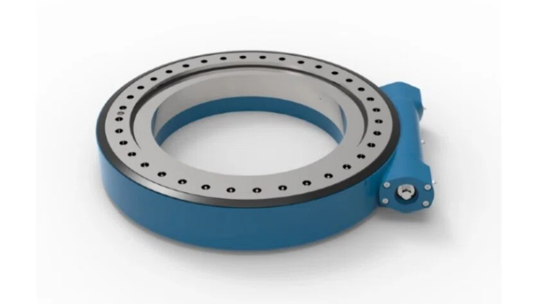
A slew drive rotary system is a compact, integrated mechanical assembly designed to manage heavy loads, provide precise rotational positioning, and simultaneously transmit electrical power, signals, or fluids across a rotating interface. Unlike basic rotary bearings, a slew drive incorporates a housing, a large-diameter bearing, and a worm gear or other gearing mechanism to actively control rotation.
In modern automation, a "slew drive rotary system" often goes further: it becomes the structural core of a rotary axis, combining load support with the ability to pass through critical utilities. This makes it a cornerstone for applications such as robotic positioners, assembly turntables, and inspection carousels. By centralizing rotation control and utility transfer, a slew drive-based system reduces mechanical complexity and improves overall machine reliability.
Core Components: Slew Drive, Slip Ring & Rotary Union
Three core technologies form the backbone of a fully capable rotary automation module:
Slew Drive: Provides structural support for axial, radial, and moment loads. It houses the bearing and drive mechanism (often a worm gear) that enables controlled, continuous rotation with high positioning accuracy and self-locking capability.
Slip Ring: An electromechanical device that transmits electrical power and data signals across the rotating interface. It prevents wire twisting during endless rotation, allowing sensors, actuators, and controllers on the rotating side to communicate seamlessly with the stationary machine frame.
Rotary Union: A precision seal assembly that transfers fluids—hydraulic oil, pneumatic air, or coolants—from a stationary source to rotating tooling or clamps. It maintains pressure and prevents leaks while accommodating continuous spin.
When these three components are integrated into a single assembly around a common slew drive, engineers eliminate mismatched interfaces and alignment headaches.
Key Features of Slew Drive Integrated Modules
Slew drive integrated modules offer a distinct set of engineering features that differentiate them from cobbled-together solutions:
High Load Capacity in a Compact Footprint: The slew drive’s large-diameter bearing distributes forces efficiently, supporting heavy workpieces without requiring oversized structures.
Integrated Pass-Through: A central bore or offset channels allow slip ring wires and rotary union hoses to route cleanly inside the assembly, protecting them from external damage and reducing machine envelope.
Self-Locking Capability: The worm gear design in many slew drives provides natural self-locking, holding position without constant brake engagement—critical for safety in vertical or tilting axes.
Modular Customization: Bore size, gear ratio, mounting patterns, slip ring channel count, and rotary union port sizes can all be configured per application, from low-torque inspection tables to high-torque welding positioners.
Sealed for Harsh Environments: Integrated modules typically include ingress protection (IP ratings) to resist dust, coolant, and debris common in automated cells.
These features translate directly into faster machine design and more predictable operation.
Common Slew Drive Integration Challenges
Despite their advantages, integrating a slew drive with separate slip ring and rotary union components from multiple vendors introduces recurring challenges:
Interface Mismatches: The mounting flange of a slip ring rarely aligns perfectly with the bore pattern of a slew drive. Adaptor plates add axial length, reduce stiffness, and create potential loose points.
Wiring and Hose Routing Conflicts: Electrical cables from a slip ring and fluid hoses from a rotary union must share limited space inside the slew drive’s center. Without coordinated design, chafing, pinching, or tight bend radii cause premature failures.
Alignment Sensitivity: Even slight misalignment between the slew drive’s rotation axis and the slip ring’s rotor leads to uneven wear, electrical noise, or signal loss. Achieving and maintaining alignment during machine assembly is time-consuming.
Multiple Supply Chains: Sourcing from three different suppliers means three lead times, three sets of documentation, and three points of contact for technical support—all delaying commissioning.
Maintenance Accessibility: When components are separately stacked, accessing an internal slip ring for brush replacement often requires disassembling the entire rotary axis, increasing downtime.
These challenges directly erode the engineering efficiency and reliability that automation projects demand.
Advantages of Integrated Slew Drive Systems
Shifting to an integrated slew drive system—where the slew drive, slip ring, and rotary union are engineered as a single module—delivers measurable advantages:
Reduced Design Time: Instead of solving alignment, clearance, and interface issues, engineers work with a known interface envelope and predefined load/utility capacities. This cuts weeks from mechanical design cycles.
Simplified Procurement: One component number, one supplier, one quality standard. Purchasing and inventory management become straightforward.
Improved Reliability: Integrated modules are assembled and tested at the factory, ensuring concentricity, proper sealing, and correct wire/hose routing before shipment. Field failures due to integration errors drop significantly.
Enhanced System Capability: With all three functions designed together, an integrated module can support higher electrical channel counts, more fluid circuits, and greater moment loads than a self-assembled stack—often in a smaller overall package.
Faster Commissioning: Pre-assembled and pre-tested modules reduce on-machine debugging. Automation integrators can focus on application logic rather than chasing mechanical or electrical integration issues.
For automation OEMs and system integrators, these advantages translate directly to lower project risk and higher margins.
How a Slew Drive Handles Loads & Rotation
The slew drive is the structural and motional heart of the integrated system. Its unique design enables three critical functions:
Load Management: A slew drive uses a large-diameter rolling-element bearing (often a four-point contact or cross-roller design) to simultaneously support axial loads (thrust), radial loads, and tilting moment loads. This allows a single compact component to handle the weight of a workpiece, the forces from cutting or welding, and the overturning moment from off-center tooling.
Precise Rotation Control: Most automation slew drives incorporate a worm gear slew drive. The worm (input) rotates against a gear ring (output) to achieve high reduction ratios in a single stage. This provides smooth, low-backlash motion with excellent positioning accuracy—often within fractions of a degree.
Self-Locking: Due to the worm gear’s inherent friction angle, most slew drives cannot be back-driven. Once stopped, the output holds position without power to the motor or a mechanical brake. This is invaluable for rotary axes that must resist external forces (e.g., a welding positioner holding a heavy part at an angle).
By integrating the slew drive as the base component, engineers create a stable platform that automatically aligns the subsequent slip ring and rotary union along the same true rotational axis.
How to Integrate Slew Drive with Slip Rings & Rotary Unions
Successful integration of a slew drive with a slip ring and rotary union follows a systematic process:
Step 1: Define the Rotary Axis Requirements
Begin by listing: maximum axial/radial/moment loads, required rotational speed and duty cycle, number of electrical circuits (power, signal, data, thermocouple, etc.), and number of fluid circuits (hydraulic pressure, return, pneumatic, coolant).
Step 2: Select the Base Slew Drive
Choose a slew drive size and gear ratio that meets load and torque requirements, with a center bore diameter large enough to accommodate the slip ring and rotary union.
Step 3: Specify the Slip Ring
Select a slip ring with the required number of channels, current rating, and signal integrity (shielded pairs if needed). The slip ring’s rotor must mount directly to the slew drive’s rotating flange, and its stator to the stationary housing.
Step 4: Specify the Rotary Union
Choose a rotary union with appropriate port sizes, pressure rating, and number of passages. It typically mounts inline with the slip ring, either above or below, with its rotor connected to the same rotating reference.
Step 5: Engineer the Integrated Assembly
Design a common shaft or adapter sleeve that concentrically connects the slew drive rotating flange, slip ring rotor, and rotary union rotor. The housing integrates mounting points for slip ring stator and rotary union stator. All wire and hose exits are positioned for easy routing.
Step 6: Factory Assembly & Test
The complete module—slew drive, slip ring, rotary union, and internal wiring/hoses—is assembled at the manufacturer. Runout, electrical continuity, and fluid pressure integrity are verified before shipping.
This integrated approach replaces weeks of field engineering with a single engineered-to-order module.
Why Engineers Choose Integrated Slew Drives
Automation engineers increasingly specify integrated slew drive modules over separate components for three strategic reasons:
Focus on Core Competencies: Engineers want to design the automation cell’s workflow, not solve rotary feedthrough puzzles. An integrated module handles the complexity internally, freeing engineering resources for higher-value tasks like cycle time optimization and safety system design.
Risk Mitigation: With separate components, integration risk is borne by the machine builder. With an integrated module, the supplier owns the alignment, sealing, and interface compatibility. If something fails, there is one accountable partner.
Total Cost of Ownership: While an integrated module may have a higher upfront price than the sum of low-cost separate components, it dramatically reduces engineering hours, assembly time, commissioning delays, and field service calls. For most automation projects, the total cost is lower.
Future-Proofing: Integrated modules can be designed with spare electrical channels or additional fluid passages, allowing machine upgrades (e.g., adding more sensors or a second hydraulic clamp) without replacing the entire rotary axis.
Engineers who make the switch rarely return to piecemeal integration.
LyraDrive: Get Custom Integrated Slew Drive 3D Drawings for Your Application
LyraDrive is a professional one-stop slew drive manufacturer majored in design and development, customized production, sales and service on slew drives, slewing bearings and gear rings. We understand that every automation project has unique load, space, and utility transmission requirements.
When you share your application data—including load specifications, required electrical channels, fluid circuits, and mounting constraints—our engineering team generates accurate 3D drawings of a fully integrated slew drive module. These drawings show exactly how the slew drive, slip ring, and rotary union fit together within your machine envelope.
With these 3D drawings, you can validate integration, run interference checks, and proceed to production with confidence. Our custom approach ensures faster lead times and a precise fit for your specific automation cell, eliminating guesswork and rework.
If you need a high-performance, integrated slew drive, contact LyraDrive immediately.