



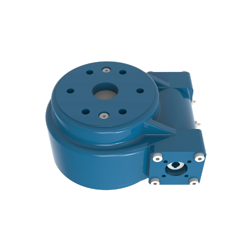
What is a slew drive? A slew drive is a compact, enclosed rotary unit that combines a slewing bearing, a gear set, and a housing. It carries axial, radial, and tilting loads while a motor turns the payload.
Here is the question we hear from motion engineers. You specified a low-backlash drive, yet the cycle time and positioning accuracy barely moved. When you choose a precision slew drive for automation, backlash is the easiest number to compare on a datasheet, but it is often not the number that limits the axis.

What a Backlash Number Tells You, and What It Leaves Out
Backlash is lost motion between gear flanks when the direction reverses. It is measured at very light load. It tells you how far the output can move before the gear teeth make contact again.
That makes it useful for axes that reverse often, or that hold a position while the load changes direction. A low backlash slew drive helps there. But backlash is free play, not elastic deflection. Once torque is applied, the gear train, housing, and bolted joints all flex, and that flex does not show up in the backlash figure.
A note on scope. Many supplier pages, including ours, describe low backlash as a headline advantage for robotics, medical imaging, and automation. That tells you how the product is marketed. It does not prove that backlash is the main limit on your axis. This article is an engineering analysis, not a market survey, and it does not rely on dated industry data.
When Low Backlash Fails to Improve Positioning
Three factors usually take over once backlash is small: torsional compliance, load inertia, and control settling time. They are linked, so fixing one without the others often changes nothing. The table shows how each one looks on a real machine.
| Limiting factor | What you see | Why a tighter backlash spec does not help | What to check first |
|---|---|---|---|
| Torsional compliance (slew drive torsional stiffness) | Position error that grows with torque or acceleration; ringing after a move | Wind-up is elastic deflection under torque. It exists even when lash is near zero. | Ask for torsional stiffness or wind-up under your peak torque, and compare it with your error budget |
| Automation load inertia | Overshoot, low servo gain, slow moves | Inertia and stiffness together set the resonant frequency. Lash does not change either one. | Calculate reflected inertia and the load-to-motor inertia ratio, including offset tooling |
| Control settling time (rotary axis settling time) | Final position is correct, but the next process step waits | Settling depends on bandwidth, damping, and resonance, not on gear free play. | Record settling time into your tolerance band and review filter and gain settings |
| Feedback location | Motor encoder reports "in position" while the output still moves | A motor-side encoder cannot see gear wind-up or mounting flex. | Compare motor-side and output-side position during a move |
This is why low backlash does not improve accuracy on many axes. The relationship is simple. Resonant frequency is roughly (1 / 2π) × √(stiffness / inertia). If you double the inertia, the frequency drops by about 29%. If you quadruple it, the frequency is cut in half.
A lower resonance forces the servo to run at lower bandwidth, and lower bandwidth means longer settling. A drive with tight lash but modest stiffness can therefore be no faster than a looser, stiffer one.
Where this does not apply. If your axis reverses at small amplitude under light load, or holds position while the load direction flips, backlash is still a real error source. Measure it before you dismiss it. The sections below show how.
Request Your Custom Slew Drive or Bearing Spec
Tell us your load, speed, and environment — receive a tailored 100–5000 mm slewing drive or slewing bearing proposal with 3D drawings within 24 hours.
Drivers and Alternative Explanations
Start by separating what you observed from what you infer. Observed: a lower-backlash drive did not shorten the cycle. Possible explanations are listed below, and several can be true at once.
- Housing and mounting flex. A mounting surface that is not flat, or bolts with uneven preload, can add compliance that no gear spec reflects.
- Compliance upstream of the slew drive. A motor, coupling, or gearbox stage ahead of the input adds its own wind-up.
- Offset or changing inertia. A tool or workpiece that sits off-center adds more inertia than the nameplate payload suggests.
- Tuning limits. Gains may have been set conservatively for an older mechanism and never revisited.
- Backlash that varies around the circle. Gear mesh is not identical at every angle, so one test position may not represent the full travel.
Common mistakes we see in specifications:
- Comparing backlash values taken under different test conditions.
- Treating "precision" as one number instead of separate lost-motion, stiffness, and repeatability values.
- Upgrading the drive before measuring output-side motion.
- Ignoring tooling inertia when sizing the motor.
A Step-by-Step Way to Find the Real Limit
- Log the move. Capture command, motor-side position, and output-side position for your real move profile.
- Split the error. Separate final static error from the time spent settling. They have different causes.
- Run a small reversal test. Measure lost motion at the output. If it is small next to your error budget, backlash is not the limit.
- Find the resonance. Use a step or frequency-response test. Compare the result with your estimate from stiffness and inertia.
- Choose the lever. Raise stiffness, reduce inertia, move the feedback to the output, or retune. Change the drive only if the evidence points there.
The limit of this method is access. If the machine is not built yet, you cannot log a move. In that case, ask your supplier for stiffness data and run the inertia calculation before you freeze the design.
What to Ask a Slew Drive Supplier Before You Buy
Your questions should map to the decisions they affect. Use this checklist.
- Torsional stiffness or wind-up at rated torque. This decides whether the drive can meet your error budget under load.
- Backlash test conditions. Ask where it was measured and whether it varies around the circle.
- Gear type. A worm gear slew drive gives self-locking and a compact package. A spur gear slew drive suits axes where efficiency and back-driving behavior matter more. Neither is better in general.
- Inspection method. Ask how each unit is verified. Our slew drive quality control process uses CMM three-coordinate inspection, and the factory is ISO 9001:2015 certified.
- Mounting requirements. Flatness and bolt preload affect stiffness in the field.
For context, here are three real cases from Luoyang Slewring Bearing Co., Ltd. They show the precision grades buyers have specified. They do not prove cycle-time results, and they are not a market trend.
- A Manchester, UK automation equipment manufacturer ordered 100 units of the SP-I slew drive (model SP-I 0841-32.1) for automated turntable systems.
- A British Columbia, Canada forestry equipment manufacturer ordered 30 units of the WED14-86-25BHR.5 double worm drive for grapple machines, with precision of 0.13° or better. See our double worm slew drive range.
- A South Korean port equipment manufacturer placed a repeat order of 20 WEA9-62-25HR single worm drives for port cranes, with tracking precision of 0.15° or better, IP65 sealing, and self-locking.
If your axis needs a different stiffness, ratio, or interface, a customized slew drive may fit better than a catalog size. Our standard MOQ is 1 set and our customized MOQ is 5 sets. We can return a technical proposal within 24 hours, and 3-day rapid prototyping is available for evaluation.
Uncertainty and Signals That Would Change the Assessment
There is no public dataset we can cite that shows how often backlash is the true limit on automation axes. The answer depends on your inertia, your servo, and your mounting. Treat this article as a framework for testing, not a verdict.
These signals would change the conclusion:
- Output lost motion is close to your error budget. Backlash is the limit, and a lower-lash drive is justified.
- The measured resonance sits near your servo bandwidth. Stiffness or inertia is the limit. Look at drive size, gear type, or the mounting design.
- Settling improves after retuning or an output-side encoder. The mechanism was not the problem.
- Error appears only at one angle. Check gear mesh variation and mounting flatness before changing the product.
When you ask a supplier to quote a precision slew drive for automation, send the load inertia, peak torque, move profile, tolerance band, and mounting interface. With those five inputs, an engineer can judge whether stiffness, backlash, or something outside the drive is setting your cycle time. Our 48-hour technical response and 2-year extended quality warranty apply to confirmed orders.
Request Your Custom Slew Drive or Bearing Spec
Tell us your load, speed, and environment — receive a tailored 100–5000 mm slewing drive or slewing bearing proposal with 3D drawings within 24 hours.
 WhatsApp

 +8613903880726