


Influence of rotational inertia on the slew drive transmission performance
Introduction
Slew drives are critical components in modern mechanical systems, enabling precise rotary motion and load handling. Their transmission performance directly impacts the efficiency, accuracy, and reliability of the equipment they power. At LyraDrive, we recognize that various external conditions can influence this performance. Through close communication with our customers and a deep understanding of their specific operating conditions, we design high-quality, tailored solutions. This article explores one crucial factor affecting slew drive performance—rotational inertia—to provide valuable insights for your selection process.
What Is a Slew Drive?
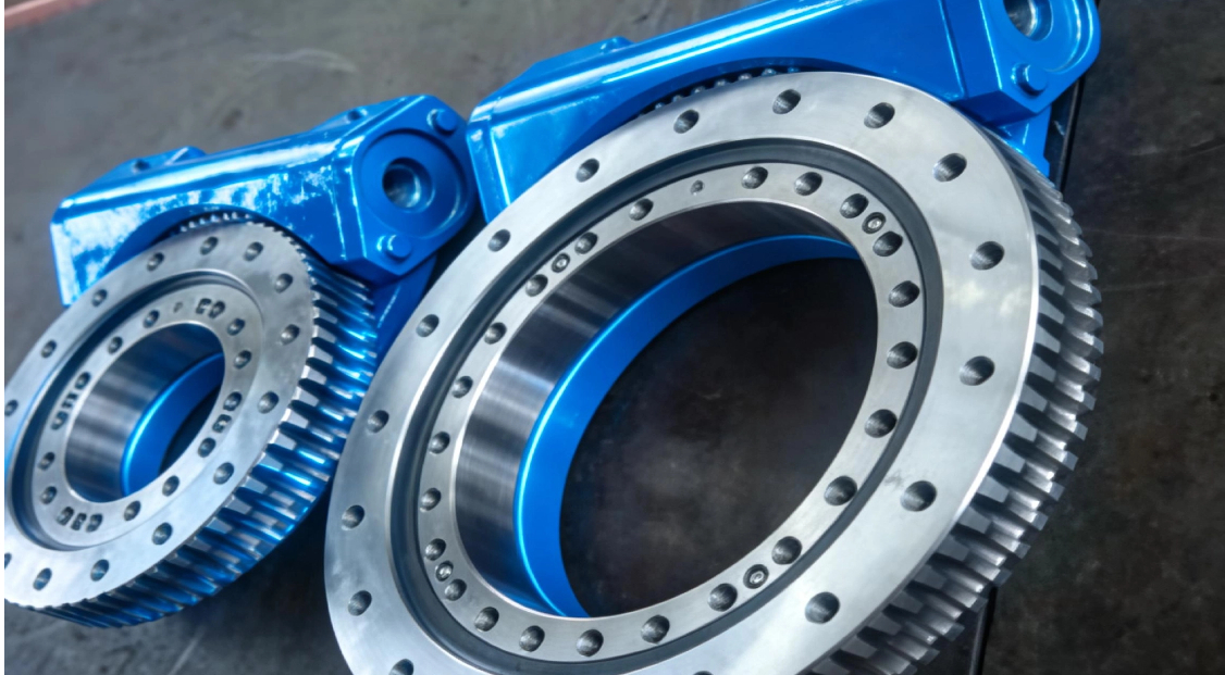
A slew drive is a compact gearbox designed to handle radial, axial, and moment loads while providing controlled rotary motion. It typically consists of:
A slewing bearing with integrated inner and outer rings and rolling elements
A drive mechanism such as a worm gear, spur gear, or double worm system
A protective housing that encloses and seals the internal components
Slew drives are widely used in applications requiring precise positioning, high load capacity, and reliable performance under challenging conditions. Their ability to simultaneously support heavy loads and provide accurate rotation makes them indispensable in modern mechanical systems.
Key Design Features of Slew Drives
Modern slew drives incorporate several design features that enhance their performance and durability:
Integrated Slewing Bearing combines bearing and gear functions in one unit, enabling compact design and high load capacity while reducing overall system complexity.
Hardened Gear Teeth provide surface-hardened gears for exceptional wear resistance, extending service life significantly even under continuous operation.
Sealed Housing protects internal components from contaminants such as dust, moisture, and debris, improving reliability in harsh environmental conditions.
Preload Adjustment allows optimization of gear mesh clearance, reducing backlash and increasing positioning precision for demanding applications.
Multiple Mounting Options offer flexible configurations for various applications, making integration into existing systems straightforward and efficient.
These design elements work together to ensure smooth, efficient power transmission across diverse operating conditions and load requirements.
How Does a Slew Drive Work?
Understanding the working principle of a slew drive is essential for appreciating the role of rotational inertia. The operation can be broken down into several key stages:
Power Input begins when an external motor or hydraulic drive provides rotational power to the input shaft of the slew drive. This input shaft is connected to the drive mechanism, such as a worm or pinion gear, establishing the first point of energy transfer.
Gear Engagement occurs as the input gear meshes with the gear teeth on the slewing bearing's inner or outer ring. This precision engagement transfers rotational motion from the input to the output while maintaining smooth contact throughout the rotation cycle.
Motion Transmission happens as the input gear rotates, driving the slewing bearing ring and causing the attached load to rotate. The gear ratio, determined by the number of teeth on each gear, defines the output speed and torque relative to the input.
Load Handling is continuously performed by the integrated slewing bearing, which simultaneously supports radial loads perpendicular to the axis, axial loads along the axis, and moment loads that create tilting forces. This multi-directional load capacity is a defining characteristic of slew drives.
Output Rotation is the final result—controlled, precise rotary motion of the connected equipment, whether it's a solar panel tracking the sun, an aerial lift positioning workers, or an industrial robot arm moving components through complex sequences.
Key Application Areas of Slew Drives
The robust design and precise control of slew drives make them indispensable across numerous industries:
Solar Tracking Systems
These applications require smooth, continuous motion to follow the sun across the sky for maximum energy generation. Slew drives in solar trackers must operate reliably for decades with minimal maintenance, making durability and sealing against environmental exposure critical requirements.
Construction and Aerial Lifts
Equipment such as cranes, excavators, and personnel lifts demand high load capacity, safety, and reliability under varying and often extreme conditions. Slew drives in these applications must handle shock loads, maintain positioning under heavy loads, and provide smooth operation for operator comfort and safety.
Industrial Automation and Robotics
Modern manufacturing relies on high-speed, precise motion control. Slew drives in automation applications need fast response times, high positioning accuracy, and optimized dynamic performance to support increased production throughput and quality requirements.
Wind Power Equipment
Wind turbines use slew drives for yaw control (orienting the nacelle toward the wind) and pitch control (adjusting blade angles). These applications require exceptional durability, corrosion resistance, and the ability to handle extreme environmental loads over decades of operation.
Marine and Offshore Applications
Shipboard cranes, offshore platform equipment, and marine navigation systems benefit from corrosion-resistant slew drive designs that handle heavy loads in saltwater environments where reliability is paramount for safety and operational continuity.
Key Factors Affecting Slew Drive Transmission Performance
The transmission performance of a slew drive is influenced by multiple interrelated factors. Understanding these helps in selecting the right drive for your application and optimizing its operation:
Load Conditions
Load characteristics determine stress on gears and bearings. Static loads apply constant force, while dynamic loads vary during operation. Shock loads, which occur during starting, stopping, or external impacts, can momentarily exceed design limits and must be carefully considered during selection.
Lubrication
Proper lubrication affects friction, wear, and heat generation. The choice of oil type and viscosity must match operating conditions, while maintenance intervals must ensure lubricant properties remain effective throughout the drive's service life.
Operating Speed
Rotation speed influences dynamic behavior and heat buildup within the drive. Continuous high-speed operation requires different design considerations than intermittent slow-speed positioning, affecting gear selection, lubrication requirements, and cooling needs.
Temperature
Operating temperature changes material properties and lubricant performance. High temperatures can degrade lubricants and alter gear clearances, while low temperatures increase lubricant viscosity and may require special cold-start considerations.
Mounting and Alignment
Installation precision affects load distribution and wear patterns. Misalignment during mounting can concentrate stresses on specific gear teeth or bearing areas, leading to premature failure and reduced performance.
Backlash
Gear clearance impacts positioning accuracy and system stiffness. Applications requiring precise positioning, such as robotics and automation, benefit from minimized backlash through preload adjustment and high-precision gear manufacturing.
Rotational Inertia
Among these factors, rotational inertia plays a particularly significant role in applications requiring frequent starts, stops, or speed changes—common scenarios in automation and robotics. The following sections explore this critical parameter in detail.
What Is Rotational Inertia in a Slew Drive?
Rotational inertia, also called moment of inertia, is a measure of an object's resistance to changes in its rotational motion. In the context of a slew drive, it represents how the mass of rotating components is distributed relative to the axis of rotation.
The rotational inertia of a slew drive depends on several factors:
Mass of Rotating Parts
Heavier components—including gears, shafts, and bearing rings—increase overall inertia. Every gram of material contributes to the energy required to accelerate or decelerate the system.
Mass Distribution
The distance of mass from the rotation axis significantly affects inertia. Mass located farther from the axis contributes disproportionately more to inertia, following the principle that inertia increases with the square of the distance.
Gear Geometry
Tooth size, number of teeth, and overall gear dimensions influence inertia values. Larger diameter gears with more material at greater radii have higher inertia than smaller, more compact designs.
Mathematically, for a rotating component, inertia is expressed as , where represents each mass element and its distance from the rotation axis. This fundamental relationship explains why reducing mass or bringing it closer to the axis significantly lowers inertia.
The Influence of Rotational Inertia on Transmission Performance
Rotational inertia affects several critical aspects of slew drive transmission performance:
Dynamic Response
Inertia directly determines how quickly a drive can accelerate, decelerate, or reverse direction. High inertia results in sluggish response—the system takes longer to reach desired speeds or positions. Low inertia enables rapid changes, essential for precision automation where cycle times directly impact productivity.
Energy Efficiency
During acceleration, energy is required to overcome inertia and bring rotating components up to speed. Higher inertia means more energy consumed during each start-stop cycle. In applications with frequent motion changes, this energy loss can be substantial, increasing operating costs and heat generation.
Vibration and Noise
Rotational inertia influences the natural frequencies of the drive system. When combined with other system parameters, inappropriate inertia values can amplify vibrations at certain speeds, increasing noise and potentially causing resonance issues that affect both performance and component life.
Shock Load Sensitivity
During emergency stops or sudden load changes, the inertia of rotating components generates additional dynamic loads. High inertia creates larger impact forces during braking, which can stress gears and bearings beyond their design limits, potentially causing damage or premature failure.
Positioning Accuracy
For precision applications, inertia affects how cleanly the drive settles at a target position. High inertia systems may overshoot or oscillate before stabilizing, while properly matched inertia supports crisp, accurate positioning essential for modern manufacturing requirements.
| Performance Aspect | Effect of High Inertia | Effect of Low Inertia |
|---|---|---|
| Dynamic Response | Slower acceleration and deceleration | Rapid response to speed changes |
| Energy Consumption | Higher per start-stop cycle | Lower, especially in cyclic operation |
| Vibration Tendency | Potential resonance at certain speeds | Generally smoother operation |
| Shock Load Impact | Large additional forces during braking | Reduced impact forces |
| Positioning Accuracy | Possible overshoot and oscillation | Clean, precise settling |
How to Minimize Rotational Inertia Effects in Slew Drive Design?
Controlling rotational inertia and its effects involves both design optimization and thoughtful application engineering:
Design-Level Strategies
Material Selection uses lightweight, high-strength materials for rotating components wherever possible. Advanced materials can significantly reduce mass while maintaining necessary strength and durability.
Geometry Optimization designs gears and shafts with mass concentrated near the rotation axis. This approach reduces inertia without compromising functional requirements by placing material only where structurally needed.
Component Integration combines functions to eliminate unnecessary rotating parts. Reducing the number of components in the rotating assembly directly lowers overall system inertia.
Bearing Selection chooses bearings with optimal mass characteristics for the specific application, considering the trade-off between load capacity and rotating mass.
Application-Level Strategies
Inertia Matching ensures the load inertia is appropriately matched to the drive's capabilities. Understanding the relationship between drive inertia and load inertia helps optimize system performance.
Control System Tuning adjusts acceleration profiles to work within the system's inertia characteristics. Proper tuning can minimize energy consumption while maintaining required cycle times.
Soft Start-Stop Implementation uses controlled acceleration and deceleration to manage inertia-induced loads. Gradual speed changes reduce stress on components and improve positioning accuracy.
Regular Maintenance keeps lubrication optimal to minimize additional friction that can interact with inertia effects. Well-maintained drives perform closer to their design specifications.
Consider a robotic positioning application requiring rapid point-to-point moves. A drive with optimized low inertia would reach commanded positions faster, consume less energy per cycle, generate less heat during operation, and experience lower shock loads during emergency stops—all contributing to improved productivity and extended equipment life.
LyraDrive: Get Custom Slew Drive 3D Drawing for Your Application
LyraDrive is a professional Chinese manufacturer specializing in slew drives and slewing bearings with over 15 years of industry experience. We produce a comprehensive range of slew drives, including:
Worm Gear Slew Drives for applications requiring high reduction ratios and self-locking capability
Double Worm Slew Drives for enhanced precision and reduced backlash requirements
Spur Gear Slew Drives for high-speed applications and efficient power transmission
Our extensive product line enables us to meet diverse customization requirements across various industries. Whether you need standard configurations or fully customized solutions, our engineering team works closely with you to understand your specific needs and application challenges.
Our Customization Process
When you contact us with your requirements, we begin by receiving your sample data and relevant drawings. Our engineers apply advanced 3D technology for comprehensive analysis and simulation, allowing us to evaluate critical parameters—including rotational inertia—during the design phase rather than discovering issues after manufacturing.
We then optimize the design based on your performance requirements, considering factors such as load conditions, operating speeds, and environmental challenges. This thorough approach ensures that every aspect of the drive is tailored to your application.
Finally, we deliver a custom solution that meets your exact specifications, complete with detailed documentation and support. With our 3D analysis capabilities, we ensure your final drive delivers optimal performance for your application from the first day of operation.
Contact us today to request a custom 3D drawing and start your project with confidence. Our team is ready to help you achieve the perfect balance of performance, reliability, and value for your specific requirements.
FAQs
Q1: What is the main effect of high rotational inertia in a slew drive?
A: High inertia primarily slows dynamic response, increases energy consumption during acceleration and deceleration, and can amplify shock loads during emergency stops. These effects are most significant in applications with frequent starting and stopping.
Q2: Can rotational inertia be reduced in an existing slew drive?
A: Modifying an existing drive to reduce inertia is challenging and often impractical. It's more effective to specify optimized inertia characteristics during initial selection or custom design, which is why LyraDrive emphasizes thorough analysis during the design phase.
Q3: How does rotational inertia relate to gear ratio?
A: The effective inertia seen by the motor is affected by the square of the gear ratio. This relationship is critically important when matching a motor to a slew drive, as it determines how much of the load inertia is "reflected" back to the motor.
Q4: What applications are most sensitive to rotational inertia?
A: Applications with frequent starts, stops, or reversals—such as automation equipment, robotics, packaging machinery, and high-speed positioning systems—are most affected by rotational inertia considerations.
Q5: How can I calculate the rotational inertia of my load?
A: LyraDrive's engineering team can assist with inertia calculations using your load dimensions, mass distribution data, and operating parameters during the design phase. We recommend providing as much detail as possible about your application.
Q6: Does LyraDrive offer low-inertia designs for high-speed applications?
A: Yes, we can optimize gear geometry, select appropriate lightweight materials, and tailor designs specifically for applications requiring low rotational inertia. Our engineering team will work with you to determine the best approach for your specific requirements.