



What is a slewing ring bearing for crane applications? It is the large rotational bearing that connects the crane upper structure to its chassis, pedestal, or turntable while carrying vertical weight, horizontal forces, and tilting loads at the same time.
For crane OEM engineers and maintenance teams, the selection task starts before a drawing or quotation request. You need to convert the actual load case into clear bearing inputs: axial load, radial load, overturning moment, rotation conditions, mounting dimensions, gear arrangement, and operating environment.
A bearing chosen only by outside diameter or a previous part number can fail early if the duty cycle, boom reach, load center, or mounting structure has changed. The goal is not simply to find a ring that fits. The goal is to define a bearing specification that can support the real crane duty.

Start with the crane information that affects bearing selection
Collect operating data before comparing bearing models. A catalog size is not enough because two cranes with similar platform diameters may create very different overturning moments.
For a replacement project, first confirm whether the original bearing failed because of wear, mounting distortion, lubrication loss, overload, gear damage, or an incorrect replacement part. Replacing a damaged ring with the same model does not solve a structural or load-case problem.
Prepare these inputs before requesting a bearing proposal
- Crane type and application: Identify whether the unit is a truck crane, deck crane, port crane, crawler crane, pedestal crane, or another rotating lifting machine. The application affects load direction, duty cycle, corrosion exposure, and required precision.
- Maximum lifted load: Record the rated load, lifting accessory weight, hook block weight, and any attached handling tool. These items contribute to the vertical load carried through the turntable.
- Boom geometry: Provide boom length, working radius, boom angle range, and the distance from the bearing center to each major load center. These dimensions are needed to calculate overturning moment.
- Upper structure weight: Include the cab, counterweight, winch, boom base, machinery deck, and other equipment supported above the bearing.
- Horizontal loading: Identify wind, side pulling, acceleration, braking, traveling effects, and any load swing that can create radial force.
- Rotation requirement: State intermittent or continuous rotation, expected speed range, positioning requirement, and whether the bearing uses an internal gear, external gear, or no gear.
- Mounting details: Provide bolt circle diameter, bolt quantity, mounting-hole style, gear position, center opening, ring height, and available installation space.
- Environment: Identify rain, salt spray, dust, temperature exposure, and corrosion conditions. Material and sealing choices should reflect the actual site.
Some data can be clarified later, such as final paint color or shipping configuration. Load direction, mounting dimensions, and boom radius cannot wait. Missing those inputs blocks meaningful load verification.
For mobile lifting equipment, review the mounting interface as closely as the bearing itself. A suitable Truck Crane Slewing Bearing still depends on flat, stiff upper and lower mounting surfaces. A distorted pedestal can create uneven raceway loading even when calculated crane loads are acceptable.
Convert axial, radial, and overturning moment loads into a bearing specification
The correct selection method is to list every significant operating position, calculate the load components at the bearing center, and compare the combined result with the bearing supplier’s rating data. Do not assess axial load, radial load, and moment as separate pass-or-fail items. Crane bearings usually experience them together.
| Load input | How to define it | What it changes in the specification | Common selection error |
|---|---|---|---|
| Axial load | Sum the vertical forces transmitted through the rotating upper structure, including lifted load and supported machine weight. | Determines required vertical carrying capacity and raceway contact loading. | Using rated payload only while excluding hook block, boom, counterweight, and upper structure weight. |
| Radial load | Identify horizontal forces at the bearing center from side pull, wind, acceleration, braking, or load swing. | Influences raceway loading and may affect bearing type, clearance, and mounting requirements. | Assuming radial load is zero because the crane lifts vertically during normal operation. |
| Overturning moment | Multiply each force by its perpendicular distance from the bearing center, then combine moments by direction. | Often governs bearing diameter, raceway capacity, bolt pattern, and ring section. | Using boom length instead of the actual horizontal load radius in the operating position. |
| Combined load case | Pair axial force, radial force, and moment from the same operating event. | Provides the data needed for supplier rating-curve verification. | Combining the maximum value of each load from unrelated operating conditions. |
Use this sequence for each governing load case
- Define the crane position. Set boom radius, boom angle, lifted load, upper structure orientation, and any travel or wind condition. One load case should represent one physically possible operating condition.
- Draw a free-body diagram. Mark the bearing center and every force acting above it. Separate vertical forces from horizontal forces.
- Calculate axial load. Add the vertical downward forces supported by the bearing. If a force acts upward in a special condition, keep its direction clear rather than adding it as a positive downward load.
- Calculate radial load. Combine horizontal forces by direction. A side pull and wind load can either add together or partly oppose each other, depending on crane orientation.
- Calculate overturning moment. For each force, use the basic relationship M = F × d, where F is force and d is the perpendicular distance from the bearing center. Keep clockwise and counterclockwise moments separate until the final combination.
- Identify the governing cases. The maximum lifted load may govern axial loading, while maximum boom reach may govern moment. A wind or side-pull case may govern radial loading.
- Submit combined values for rating review. Present each load case as an axial-radial-moment set, along with rotation and mounting details. The bearing supplier should check these values against product-specific allowable load curves.
A useful working format is a load-case table with one row per operating condition. Include the crane position, vertical force, horizontal force, moment direction, rotation condition, and whether the condition is normal service, occasional operation, or an abnormal event that must be excluded from normal bearing selection.
The result should be a bearing requirement, not merely a part number. A useful requirement states the bearing type, gear arrangement, mounting dimensions, combined load cases, rotational duty, environmental exposure, and inspection requirements.
At Luoyang Slewring Bearing Co., Ltd., our engineering team can review these inputs during early technical evaluation. Our facility uses CMM three-coordinate inspection and dynamic load testing for every slewing bearing, which supports dimensional and load-related quality checks before shipment.
Request Your Custom Slew Drive or Bearing Spec
Tell us your load, speed, and environment — receive a tailored 100–5000 mm slewing drive or slewing bearing proposal with 3D drawings within 24 hours.
Choose the bearing arrangement that matches the load pattern
After defining the combined loads, select a bearing arrangement based on the dominant duty. The best design is not always the largest ring. It is the arrangement that supports the load pattern, available space, rotation requirement, and mounting structure without creating unnecessary cost or complexity.
| Bearing arrangement | Best fit | Why it may be selected | When it may not fit |
|---|---|---|---|
| Single Row Slewing Ring Ball Bearings | Light to moderate crane loads with limited space and moderate moment demand. | Provides axial, radial, and moment capacity in a compact arrangement. | May not be the preferred choice for high cyclic loads or very large overturning moments. |
| Double Row Ball Slewing Ring Bearing | Applications needing increased axial load distribution and stable support. | Two ball rows can distribute loading across more raceway contact points. | It may be less suitable when a roller arrangement is required for the expected duty and moment level. |
| Crossed roller bearing | Crane systems requiring controlled rotation and high stiffness in a compact envelope. | Rollers can support loads from multiple directions with good rotational control. | Selection still requires confirmation of shock loads, mounting stiffness, and duty cycle. |
| Three-row Roller Slewing Bearings | Heavy cranes, port equipment, and applications with high combined loads. | Separate roller rows are arranged to carry axial and radial forces more directly, supporting heavy-duty load distribution. | Usually requires more space, a stronger mounting structure, and a higher equipment budget than lighter arrangements. |
Use a three-row roller arrangement when high axial force and overturning moment occur repeatedly, such as in large port crane or heavy lifting duties. This choice is justified when the load-case review shows sustained combined loading, not simply because the crane has a large outside diameter.
Use a lighter ball-bearing arrangement only when the combined load review supports it. A compact unit can be suitable for a smaller service crane, but it should not be copied into a higher-duty model with a longer boom or larger working radius.
Luoyang Slewring Bearing has supported more than 2,000 heavy-equipment projects through slewing bearing and slew drive development. For specialized layouts, a Customized Slew Drive may be evaluated when the application needs an integrated rotation drive instead of a separate bearing and drive arrangement.
Check mounting structure, gear loading, and bolt interfaces before finalizing the part
A correct bearing capacity check can still lead to poor field life if the mounting surfaces are weak or uneven. The ring must transfer load through the crane upper frame and lower pedestal without local distortion.
Ask for the available mounting drawing and check these points before final approval:
- Flatness and support: The bearing should have continuous, properly prepared support around its mounting faces. Local gaps can concentrate load into a small raceway zone.
- Bolt pattern: Confirm hole quantity, hole size, bolt circle, thread engagement, and tightening method. Do not modify a mounting hole pattern without bearing-engineering review.
- Center opening: Verify clearance for hydraulic lines, electrical cables, rotary unions, and internal structure. A large opening can affect ring stiffness and must match the approved design.
- Gear position: Confirm internal gear, external gear, or gearless configuration. The pinion location must allow correct engagement across the full rotation range.
- Drive torque: Check that acceleration, braking, and holding torque do not overload the gear teeth or create unexpected radial loading through the pinion.
- Lubrication access: Make sure grease fittings remain accessible after the crane is assembled. If technicians cannot lubricate the bearing, planned maintenance will be missed.
Gear selection is especially relevant for cranes that rotate under load. A ring gear does more than transmit motion; its pinion mesh can add radial force into the bearing system. Include drive layout and operating torque information in the technical review.
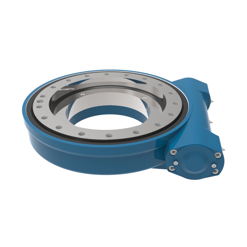
For a crane needing an integrated rotating drive, a Worm Gear Slew Drive can provide bearing support and worm-driven rotation in one assembly. It fits applications where compact drive integration and holding behavior are required, but it is not an automatic substitute for a large crane slewing bearing. The final choice depends on the full load case and required drive torque.
Use replacement bearing evidence to find the real cause of failure
For maintenance teams, the removed bearing provides useful evidence. Record the failure pattern before disposal. It can reveal whether the next bearing needs a revised specification or whether the crane structure and maintenance process need correction.
| Observed condition | Likely issue to investigate | Recovery action before replacement |
|---|---|---|
| Localized raceway damage | High moment in a repeated orientation, poor mounting support, or uneven bolt preload. | Inspect the upper and lower mounting faces, confirm crane working positions, and reassess moment load cases. |
| Gear tooth wear on one section | Incorrect pinion mesh, misalignment, poor lubrication, or repeated operation in one rotation zone. | Inspect the pinion, gear backlash setting, drive mounting, and lubricant condition. |
| Loose mounting bolts | Incorrect tightening practice, joint settlement, vibration, or mounting face distortion. | Review the bolt tightening procedure and inspect bolt holes, threads, and supporting structure. |
| Corrosion or contaminated grease | Damaged seals, inadequate protection, or unsuitable service conditions. | Inspect sealing, grease condition, washdown exposure, and corrosion protection requirements. |
| Abnormal rotational resistance | Raceway damage, structural deformation, inadequate lubrication, or drive misalignment. | Measure rotation resistance after checking the mounting structure and removing drive-side interference. |
Do not treat all play or noise as bearing failure. Check the pinion, gearbox, mounting bolts, frame condition, and lubrication first. The bearing should be inspected as part of the complete slewing system.
For example, a truck-mounted crane that has been modified with a longer boom or a larger lifting attachment may experience higher overturning moment even if the rated payload has not changed. In that case, the replacement decision should return to the load-case calculation rather than relying on the original bearing reference alone.
Verify the selection package before requesting drawings or a quotation
Before releasing a request for quotation, confirm that your technical package allows the supplier to perform a meaningful review. A clear package reduces revision cycles and helps prevent an unsuitable bearing from being quoted only because it matches a requested diameter.
Final buyer and engineering checklist
- Have axial load, radial load, and overturning moment been calculated for each governing crane position?
- Does each combined load set represent one real operating condition?
- Have boom radius, load center, upper structure weight, and counterweight been included?
- Are normal operating loads separated from unusual or excluded conditions?
- Are the bearing outside diameter, inside diameter, height, center opening, mounting holes, and gear arrangement defined?
- Has the upper and lower mounting structure been checked for adequate support and condition?
- Are rotation speed, duty cycle, gear drive details, lubrication access, and environment stated?
- For a replacement, have photos and notes from the removed bearing been retained?
- Has the supplier been asked to confirm suitability against combined load curves rather than individual loads only?
Luoyang Slewring Bearing Co., Ltd. operates an ISO 9001:2015 certified quality management system and provides CE marking for the European market. Standard products can be ordered from one set, while customized products start from five sets, which can help OEM teams evaluate a design before a larger release.
For projects that require a modified ring, our engineering team can provide a technical proposal within 24 hours when the necessary load and mounting inputs are available. Factory audit reports are also available on request, and confirmed manufacturing defects are covered by a 2-year extended quality warranty.
A completed selection package should let a supplier identify the bearing arrangement, verify the combined load cases, review the mounting interface, and prepare an accurate drawing proposal. If any one of those items remains uncertain, revisit the load-case sheet before approving the crane bearing design.
Request Your Custom Slew Drive or Bearing Spec
Tell us your load, speed, and environment — receive a tailored 100–5000 mm slewing drive or slewing bearing proposal with 3D drawings within 24 hours.
 WhatsApp

 +8613903880726