



What is a crane slew bearing? It is a large rolling-element bearing that connects a crane’s rotating upper structure to its base. It allows controlled rotation while carrying vertical weight, side force, and the tipping force created when a boom lifts a load away from the centerline.
A crane slew bearing does not handle these forces one at a time in real operation. Hoisting, boom luffing, slewing acceleration, wind, and uneven ground can act together. The correct bearing is therefore selected from combined load cases, not from the maximum lifted weight alone.
For crane designers and maintenance engineers, the main question is simple: can the bearing raceways, rolling elements, mounting bolts, and supporting structures safely carry the worst expected combination of axial load, radial load, and overturning moment? The answer depends on where each load enters the bearing and how the crane duty cycle changes that load over time.
At Luoyang Slewring Bearing Co., Ltd., our engineering team supports bearing and drive selection from early drawing review through production. Our ISO 9001:2015 certified facility uses CMM three-coordinate inspection, and each slewing bearing is subject to dynamic load testing as part of our stated quality control process.
Author: Lewis, Senior Mechanical Design Engineer, with more than 30 years of heavy machinery and power transmission design experience.
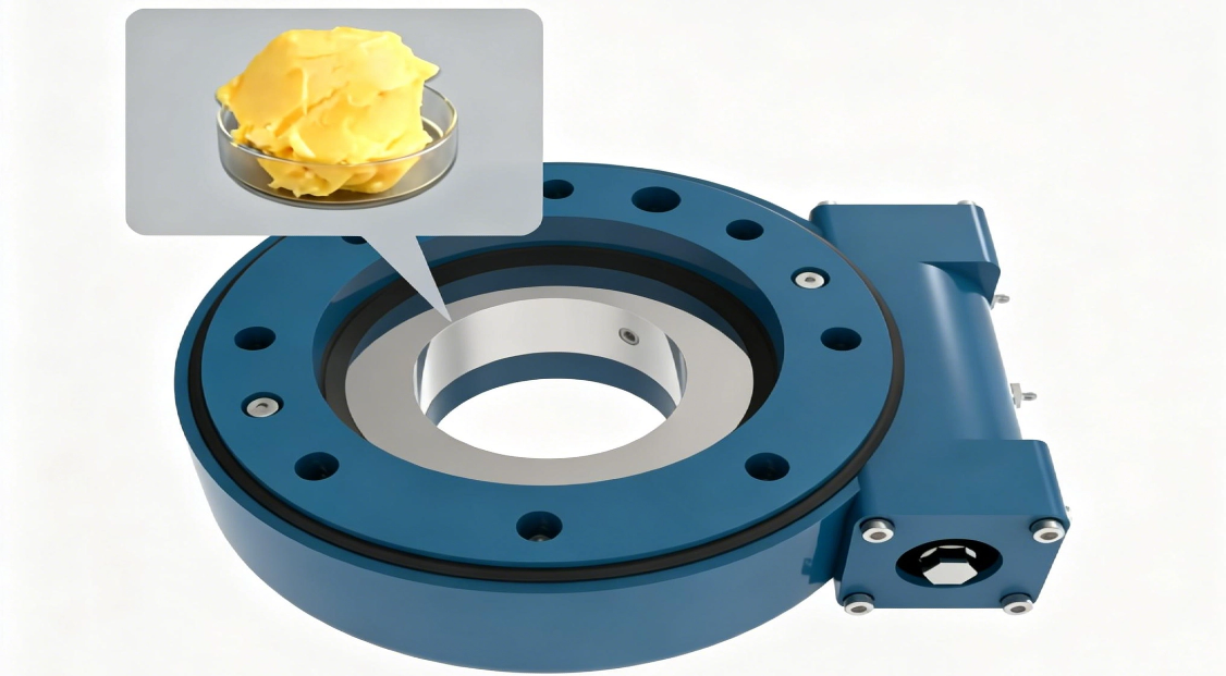
Start With the Actual Crane Load Case Instead of Rated Hoist Capacity
The first selection mistake is treating the crane’s rated load as the bearing load. A rated hook load is only one part of the force system. The bearing also carries the boom weight, counterweight effect, upper-frame weight, attachment weight, and force generated by the distance between the load and the bearing center.
The practical conclusion is to build load cases around crane positions, not just around lifting capacity. This approach fits new crane design, replacement bearing evaluation, and modification work such as fitting a longer boom or a heavier grab. It does not replace a supplier’s calculation because the bearing load rating must still be checked against the actual bearing geometry and raceway design.
Identify the operating positions that create different bearing loads
- Boom retracted with a heavy hook load: This may create high axial force because much of the load acts downward near the machine center. It may not create the highest overturning moment.
- Boom extended at working radius: The vertical load acts farther from the rotation center. The overturning moment can become the governing condition even if the hook load is lower.
- Slewing during a lift: Acceleration and deceleration introduce horizontal force and can increase radial loading. This condition matters when the crane rotates loaded rather than positioning only after the load is set down.
- Wind-exposed boom or suspended load: Wind adds side force and may increase overturning effect. This case needs site-specific wind assumptions from the crane designer or operating rules.
- Travel, rail movement, or uneven support: Structural distortion can change how load transfers through the mounting faces. A bearing selected only from ideal static calculations may be unsuitable for this condition.
For each case, document boom angle, working radius, lifted load, attachment weight, slew speed, acceleration behavior, wind condition, and the crane’s support configuration. If any of these inputs are unknown, the bearing selection remains provisional. A supplier can calculate capacity only from the information supplied.
For mobile applications, a bearing designed for a truck crane may need different checks from one used in a fixed pedestal crane. The available mounting space, bolt circle, structural stiffness, and travel-induced loads can all differ. See our Truck Crane Slewing Bearing information for product background relevant to mobile lifting equipment.
Compare Axial, Radial, and Overturning-Moment Load Paths Before Selecting a Bearing
Each load type reaches the slewing ring through a different path. Their interaction determines contact stress in the raceways, rolling-element loading, deformation of the mounting structure, and demand on the bolt joint. No single load should be judged in isolation when the crane works at radius.
| Load type | How it enters the bearing | What it affects in practice | Selection concern |
|---|---|---|---|
| Axial load | Acts parallel to the bearing rotation axis, usually from upper-structure weight, boom weight, and lifted load. | Transfers through the raceways and rolling elements as vertical support force. | High axial load can govern when the crane carries substantial dead weight near the rotation center, but it may not represent the worst extended-boom condition. |
| Radial load | Acts perpendicular to the rotation axis, often from slewing motion, wind, side pull, or machine movement. | Can shift rolling contact and increase side loading on the raceway system. | Radial load should be assessed when the crane slews under load, operates in wind, or experiences horizontal force from its duty cycle. |
| Overturning moment | Occurs when a force acts at a distance from the bearing center, such as a lifted load at boom radius. | Increases loading on one side of the raceway while reducing loading on the opposite side. | This is commonly the governing crane condition because it reflects both load magnitude and working radius. It must be checked with the matching axial and radial load. |
Overturning moment is not a separate weight sitting on the bearing. It is the turning effect produced by force acting through a lever arm. A lighter load far from the center can impose a more demanding moment than a heavier load positioned close to the crane’s slew center.
A practical combined-load selection method
- List the operating cases. Include lift, boom position, load radius, slew direction, wind condition, and machine support condition.
- Calculate or obtain axial force. Include supported dead weight and applied lifting load that transfer through the rotating structure.
- Determine radial force. Include horizontal forces caused by motion, side loading, or environmental conditions where applicable.
- Determine overturning moment. Use the relevant vertical and horizontal forces with their distances from the bearing center.
- Pair the values from the same case. Do not combine the highest axial load from one condition with the highest moment from an unrelated condition unless both can truly occur together.
- Compare each load combination with the supplier’s rating data. The bearing supplier should assess the combined values against the applicable static and operating rating method.
- Check the full interface. Review mounting bolts, bolt preload, support flatness, ring gear loading where used, and upper/lower frame stiffness.
The key limit is that a load rating chart cannot correct a weak crane structure. If the mounting faces distort, the ring can be forced out of its intended support plane. That can create uneven raceway loading even when the calculated bearing load appears acceptable.
For high-load crane duties, bearing construction matters. A Three-row Roller Slewing Bearing separates load paths more clearly than many compact bearing arrangements, which can be useful where axial, radial, and moment loads are all substantial. It is not automatically the best choice, however, because available installation space, cost, rotation requirements, and mounting design still control the final decision.
Request Your Custom Slew Drive or Bearing Spec
Tell us your load, speed, and environment — receive a tailored 100–5000 mm slewing drive or slewing bearing proposal with 3D drawings within 24 hours.
Understand How Bearing Type Changes Combined-Load Behavior
Different slewing bearing designs distribute loads differently. The best option depends on the load mix and installation envelope, not on the assumption that a larger or more complex bearing is always better.
| Bearing approach | Typical combined-load use | Practical advantage | Limit to check |
|---|---|---|---|
| Single-row ball arrangement | Compact cranes and applications with moderate combined loading. | Can provide a space-efficient solution where installation weight and size matter. | Capacity must be verified carefully when moment loading rises at long boom radius. |
| Double-row ball arrangement | Applications requiring greater load distribution than a compact single-row arrangement. | Can suit equipment where load sharing and bearing height are part of the design decision. | It still requires a combined-load check; two rows do not remove the need to assess moment load. |
| Crossed-roller arrangement | Applications requiring controlled rotational support under combined loads. | Roller orientation can support combined force directions in a compact ring structure. | Mounting accuracy and structural stiffness remain important to preserve intended load distribution. |
| Three-row roller arrangement | Heavy-duty cranes and equipment with substantial combined axial, radial, and moment loads. | Separate roller rows can be arranged for distinct load directions. | The larger installation and support design must be justified by the duty and available space. |
A compact bearing is attractive when the crane has restricted installation space. The trade-off is that concentrated combined loading may leave less room for design margin. A larger-duty bearing can support more demanding conditions, but it increases mass, cost, and integration work.
Luoyang Slewring Bearing Co., Ltd. selects ductile cast iron, alloy steel, stainless steel, or forged alloy steel according to load, speed, and environment. Material selection should follow the duty requirement. Stainless steel, for example, should not be specified only because corrosion is a concern if the total load case and required ring strength point to another suitable material strategy.
For projects needing low-speed rotation with integrated gearing and a drive housing, a Worm Gear Slew Drive may be evaluated alongside a separate bearing and drive arrangement. This solution is suitable only when its output torque, holding behavior, gear interface, and environmental protection fit the crane’s operating requirements.

Do Not Ignore the Mounting Bolts and Support Structure
The bearing does not work alone. During an overturning load, one side of the slewing ring interface is driven into compression while the opposite side can place greater demand on the mounting bolts. The upper and lower frames must keep the bearing supported around its mounting surfaces.
The clear recommendation is to evaluate the bearing, bolts, and supporting structure as one assembly. This fits both original equipment design and replacement work. It does not mean that a bearing supplier can approve a crane structure without receiving drawings, bolt details, material data, and the actual load cases.
Check these interface conditions before approving a replacement
- Bolt specification and quantity: Confirm that bolt type, engagement, tightening method, and layout match the approved design. A replacement ring should not be installed with unverified substitute bolts.
- Mounting-face condition: Inspect for corrosion, weld spatter, dents, local high spots, and deformation. Uneven contact can concentrate load into part of the ring.
- Ring gear condition: If the bearing includes external or internal gearing, inspect tooth wear and verify mating pinion engagement. Gear problems can introduce abnormal drive force.
- Structural cracking: Inspect the upper frame, turret, pedestal, and bolt area. A cracked or flexible support can change the calculated load path.
- Lubrication condition: Follow the equipment manufacturer’s lubrication practice and examine lubricant for contamination or abnormal debris.
- Measured movement: Compare measured bearing clearance or movement with the equipment manufacturer’s service limits. Do not condemn a ring from feel alone.
A common misunderstanding is that excessive play always proves the bearing is the only failed part. Wear may be present, but loose bolts, damaged mounting faces, frame distortion, or gear backlash can produce similar symptoms. Inspection should separate these causes before a replacement order is released.
Use Duty Cycle Evidence to Set the Right Selection Boundary
The worst static lift is not always the condition that determines service life. A crane that repeatedly slews with a suspended load can apply many cycles of combined radial force and overturning moment. Another crane may lift a high load rarely but remain stationary during hoisting. These machines need different evaluation emphasis.
Specify the duty cycle in plain operational terms. State how often the crane rotates under load, whether loads are lifted at full radius, whether starts and stops are frequent, and whether side loading occurs. This gives the supplier a usable basis for recommending a Heavy load slewing bearing or another arrangement.
Worked application example for a port crane
Consider a crane that lifts a load at extended radius, then slews to transfer that load. The lifted mass contributes axial force. The distance from the slew center creates overturning moment. Slewing acceleration and any wind-related side force add radial loading.
The selection method is to calculate this loaded-slew condition as one combined case, then compare it with a parked maximum-lift case and a wind-exposed condition. The governing case may differ between bearing raceway capacity, bolt loading, and drive torque. That is why a single “maximum load” statement is not enough for a final bearing choice.
Real operating context also matters. A South Korean port equipment manufacturer placed a repeat order for 20 WEA9-62-25HR single worm slew drives for port crane systems. The stated application required self-locking behavior, IP65 sealing, and tracking precision of no more than 0.15 degrees. This example supports evaluating the whole slewing system, including bearing and drive requirements, rather than treating rotation support as an isolated component.
Our production capability supports both standard and custom projects: standard products have an MOQ of 1 set, while customized products have an MOQ of 5 sets. Luoyang Slewring Bearing Co., Ltd. also provides a technical proposal within 24 hours when the needed operating data, drawings, and load information are available. A two-year extended quality warranty and a 48-hour technical response apply under our stated quality terms.
Prepare These Inputs Before Asking for a Combined-Load Assessment
A useful supplier inquiry should allow an engineer to reproduce the load path, not guess it. The more complete the input package, the more reliable the bearing recommendation and quotation will be.
- Crane type, application, and required rotation range
- Maximum lifted load and all supported dead weights
- Boom geometry, working radii, and load center locations
- Axial load, radial load, and overturning moment for each operating case, if already calculated
- Slewing speed, acceleration behavior, and expected duty cycle
- Wind, temperature, corrosion, contamination, and installation environment
- Existing bearing drawing, mounting dimensions, ring gear data, and bolt details for replacement projects
- Upper and lower mounting structure drawings or enough dimensions to review support conditions
- Required inspection documents, production schedule, and sample needs
When the application has unusual space limits, high cyclic loading, or nonstandard interfaces, a Customized Slew Drive or custom bearing proposal may be more appropriate than adapting a catalog model. The limit is clear: customization still requires confirmed load cases and interface details.
The right specification process is not “choose the biggest ring.” It is to identify the real combined load cases, verify the load path through the bearing and structure, and compare those cases with supplier-approved rating data. That process helps crane teams select a bearing that fits the machine’s actual work rather than only its headline lifting capacity.
Request Your Custom Slew Drive or Bearing Spec
Tell us your load, speed, and environment — receive a tailored 100–5000 mm slewing drive or slewing bearing proposal with 3D drawings within 24 hours.
 WhatsApp

 +8613903880726