



When crane rotation becomes slow, jerky, noisy, or hard to start, the first question is simple: is the resistance coming from the hydraulic circuit, the motor, or the slew assembly? Crane slew drive troubleshooting should answer that question before a technician removes hoses, opens a gearbox, or dismantles a bearing assembly.
A pressure gauge alone can show that the system is working hard, but it cannot prove why. A motor-current reading adds a second view of the same event. When pressure, current, rotation speed, temperature, and noise are compared under the same operating condition, a service team can narrow the fault to the correct system boundary.
This article gives a field sequence for electrohydraulic crane systems where an electric motor drives the hydraulic pump or rotation circuit. For engine-driven cranes, the pressure steps still apply, but motor-current readings may need to be replaced by engine-speed, pump-flow, or control-signal checks specified by the crane manufacturer.

Prepare the test so the readings can be trusted
Do not begin with the crane under a suspended load. Park on firm, level ground, lower or secure the boom according to the equipment manual, isolate nearby personnel, and follow the crane manufacturer’s lockout and pressure-release procedure. Hydraulic oil under pressure can cause serious injury, and an unsecured upper structure can rotate unexpectedly.
The test result is only useful if every reading is taken under repeatable conditions. Record oil temperature, ambient conditions, boom position, load status, rotation direction, and the commanded rotation speed. A cold oil reading cannot be compared directly with a reading taken after prolonged operation because oil viscosity changes resistance throughout the circuit.
Required tools and access points
- Pressure gauge or approved pressure transducer: Connect only to the crane manufacturer’s designated rotation-circuit test port. The gauge range must suit the machine’s documented system pressure.
- Clamp meter: Use it on the correct electrical conductor for the electric hydraulic pump motor or electric rotation motor. Confirm whether the system uses AC, DC, or variable-frequency control before selecting the meter mode.
- Temperature tool: An infrared thermometer can identify relative heat differences at the motor, valve block, gear housing, and bearing area. It does not replace a fluid-temperature measurement when the OEM requires one.
- Rotation timing method: Use a marked reference point on the upper structure and record the time needed for a fixed rotation angle or one complete turn when this is permitted by the crane manual.
- Machine documentation: Keep the hydraulic schematic, electrical diagram, approved pressure values, and normal current values available. These references are required for a pass-or-fail decision.
- Inspection equipment: Use a light, cleaning materials, and a camera to document leaks, loose mounting bolts, damaged wiring, and grease condition.
The most common setup mistake is comparing readings from different modes. For example, pressure recorded at a high-speed rotation command cannot be judged against current recorded at low speed. Use the same direction, command level, and machine condition for every paired reading.
Before testing, inspect the visible parts of the Slew Drive, hydraulic motor, hoses, valve block, and mounting interface. Look for external leakage, hose kinks, crushed lines, loose electrical terminals, damaged connectors, abnormal grease discharge, or a gear housing that is much hotter than nearby components after operation.
Separate hydraulic resistance from mechanical drag with a pressure and current field test
This workflow uses paired hydraulic pressure and motor-current readings to identify where resistance is being created. The method works best when readings are compared with the crane manufacturer’s baseline values or with documented readings from the same machine when it was operating normally.
| Test condition | Pressure observation | Motor-current observation | Likely direction of investigation |
|---|---|---|---|
| Normal rotation speed and smooth motion | Within documented operating range | Within documented operating range | No fault confirmed by this test; continue only if noise, leakage, or intermittent behavior remains. |
| Slow rotation with high pressure | Higher than the machine baseline | Current near normal | Hydraulic restriction, relief-valve behavior, hose restriction, valve-spool issue, or pressure-side circuit resistance. |
| Slow rotation with high pressure | Higher than the machine baseline | Higher than the machine baseline | High total load; examine both hydraulic resistance and mechanical drag before removing the slew assembly. |
| Slow rotation with normal or low pressure | Near normal or below expected working level | Higher than the machine baseline | Electric motor, pump drive, electrical supply, control setting, or motor efficiency issue may be limiting output. |
| Jerky motion and fluctuating readings | Pressure rises and drops repeatedly | Current rises and drops repeatedly | Intermittent sticking, trapped contamination, unstable control valve action, damaged wiring, or uneven mechanical resistance. |
| High pressure with poor rotation response | Pressure reaches relief behavior quickly | Current rises during demand | Mechanical binding, excessive gearbox resistance, bearing damage, overload, or a blocked hydraulic path. |
Step-by-step field procedure
- Warm the machine to its normal service condition. Operate only as permitted by the crane manual until hydraulic oil and the rotation system are at a stable working condition. Record the oil temperature before the timed test begins.
- Install the pressure instrument at the approved rotation test point. Check fittings for leakage before placing any person near the crane. Never loosen a pressurized fitting to “check” for flow.
- Install the clamp meter on the identified motor conductor. Zero the meter if required, confirm the correct measurement mode, and keep the meter location unchanged for all readings.
- Run unloaded rotation in one direction. Use a fixed command setting and time the rotation over the same marked angle each time. Record pressure, current, motion quality, and unusual sound.
- Repeat in the opposite direction. Directional differences matter. A fault appearing only in one direction often points toward a directional control valve, hose routing issue, motor port issue, or localized mechanical damage.
- Repeat with the approved working condition. If the OEM procedure permits a defined operating load or boom position, repeat the same timed rotation test. Do not create an unapproved overload simply to force a fault.
- Compare the paired readings. Match each pressure reading with the current reading taken at the same instant. Then compare both against the machine baseline and the opposite rotation direction.
- Stop if temperature, noise, or motion worsens quickly. A rising temperature trend, grinding sound, sudden current increase, or abrupt loss of rotation is a reason to stop testing and prevent secondary damage.
A successful test creates a clear pattern, not just a single number. For example, if clockwise rotation takes longer than counterclockwise rotation and both pressure and current rise only clockwise, the resistance is likely real rather than a gauge error. The next step is to determine whether the resistance remains when the hydraulic circuit is isolated from the mechanical assembly under an OEM-approved procedure.
Do not disconnect the motor from the slew drive or bypass a relief valve without the equipment manufacturer’s approved instructions. Those actions can create uncontrolled movement, release stored hydraulic energy, or damage the drive.
Request Your Custom Slew Drive or Bearing Spec
Tell us your load, speed, and environment — receive a tailored 100–5000 mm slewing drive or slewing bearing proposal with 3D drawings within 24 hours.
Use the reading pattern to choose the next inspection point
The correct repair path depends on the pattern found in the field test. High pressure does not automatically mean a damaged bearing, and high current does not automatically mean an electrical motor failure. Read the symptoms as a group.
When pressure is high but current remains near normal
Start with the hydraulic circuit. This pattern fits a restriction that raises pressure without making the electric motor work far above its normal load. Check the rotation control valve, valve spool movement, return line condition, hose routing, filters specified for the circuit, and relief-valve operation against the OEM manual.
This finding does not rule out mechanical drag. A hydraulic pump or motor may still be delivering limited flow, and a normal current reading can be misleading if the electrical supply is unstable or the meter is on the wrong conductor. Verify supply voltage and measurement location before replacing hydraulic components.
When pressure and current both rise during slow rotation
Inspect for a combined-load condition. Hydraulic pressure is rising because the system sees resistance, while current is rising because the electric drive is working harder to produce hydraulic output. Start with simple external causes: an unapproved load position, inadequate lubrication, visible gear damage, mounting distortion, or a brake that is not fully releasing.
If these checks do not explain the reading, plan a mechanical assessment of the drive and bearing interface. A Slewing Bearing can create abnormal turning resistance when internal damage, mounting problems, contamination, or lubrication issues are present. The test does not identify the exact internal defect; it identifies that mechanical resistance remains a credible cause.
When current rises but pressure does not reach the expected working level
Focus on electrical input, motor condition, pump coupling, or output flow. Check for loose terminals, damaged cables, incorrect control settings, supply-voltage loss, and motor overheating. For variable-speed drives, compare the command signal, drive fault history, and actual motor response using the crane manufacturer’s diagnostic procedure.
This result is less useful on engine-driven hydraulic cranes because engine load is not measured with a clamp meter in the same way. In that case, use the OEM’s flow, engine-speed, or pump-case-drain procedure rather than trying to apply an electric-motor conclusion.
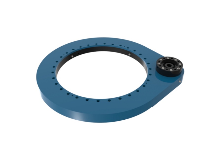
Rule out common false diagnoses before scheduling teardown
A teardown costs time and can create new alignment or contamination risks. Before opening a slew assembly, eliminate faults that can imitate internal gear or bearing damage.
- Cold oil mistaken for mechanical drag: If symptoms improve as oil warms, compare readings only after a stable warm-up condition. Cold oil can increase circuit resistance and make rotation appear mechanically tight.
- Wrong test port: Pressure measured upstream of a valve does not show the same condition as pressure at the motor port. Confirm the schematic and port label before drawing conclusions.
- One-direction test only: A directional fault may disappear when only one rotation direction is tested. Record clockwise and counterclockwise results.
- Unmatched command settings: Different joystick travel, controller settings, or rotation-speed modes produce different pressure and current readings. Use a fixed command method.
- Loose wiring treated as motor failure: A poor terminal or damaged connector can increase current, reduce motor output, and cause intermittent jerking. Inspect electrical connections before condemning the motor.
- Ignoring the brake or lock mechanism: A brake that drags or releases late can cause high-effort rotation. Verify the release command and mechanical movement using approved service instructions.
- Replacing a slew drive without checking mounting condition: Distorted mounting surfaces, loose fasteners, or structural deformation can transfer abnormal load into a replacement unit.
For crane applications that need high holding torque and controlled rotation, the drive configuration also matters. A Worm Gear Slew Drive may have self-locking characteristics in a documented application, but technicians should never treat self-locking as a substitute for the crane’s required brake, load-holding, or safety system.
Escalate to component inspection when the field test points to mechanical resistance
Schedule a closer inspection when paired readings remain abnormal after verified hydraulic and electrical checks, when one direction is consistently worse, or when noise and temperature indicate a progressing fault. The purpose is not to dismantle every slow system. It is to inspect the assembly only after the field evidence supports that decision.
Mechanical inspection checklist
- Check mounting bolts and structure for looseness, movement marks, corrosion, or distorted contact surfaces.
- Inspect exposed gear teeth for uneven wear, broken tooth edges, contamination, and poor grease coverage.
- Check grease points and lubrication condition according to the crane maintenance schedule.
- Listen for repetitive clicking, grinding, or a noise that occurs at the same rotation position.
- Inspect the hydraulic motor mounting, coupling, and drive interface for looseness or misalignment.
- Document the angle where jerking, noise, or resistance occurs. A repeatable location can help distinguish localized gear or bearing damage from a general hydraulic issue.
- Preserve pressure, current, temperature, and timing records for the engineering review.
Luoyang Slewring Bearing Co., Ltd. supports both standard and Customized Slew Drive requirements. Material selection can be matched to load, speed, and environment using ductile cast iron, alloy steel, stainless steel, or forged alloy steel where appropriate. A replacement decision still needs the machine’s mounting dimensions, load condition, rotation duty, drive arrangement, and measured fault evidence.
Our ISO 9001:2015 certified facility uses CMM three-coordinate inspection and dynamic load testing for every slewing bearing. For confirmed manufacturing defects, we provide a 2-year extended quality warranty and a 48-hour technical response. These controls are relevant when a service team needs traceable inspection support, but they do not replace correct installation or the crane manufacturer’s maintenance requirements.
Document the result for repair approval or replacement sourcing
A service manager or buyer should be able to review the test without repeating it. Prepare a short fault record that states the machine model, serial number, slew-drive identification, operating condition, test-port location, pressure result, current result, oil temperature, direction of rotation, and observable symptoms.
| Record item | Why it matters | Decision supported |
|---|---|---|
| Pressure and current taken at the same time | Shows whether hydraulic demand and electrical load rise together | Hydraulic, electrical, or mechanical investigation path |
| Clockwise versus counterclockwise results | Reveals directional valve, hose, motor-port, or localized mechanical issues | Targeted inspection rather than full teardown |
| Rotation timing at a fixed command | Converts “slow rotation” into a repeatable observation | Repair verification after corrective work |
| Temperature and sound observations | Provides supporting evidence for friction, bypassing, or electrical heating | Stop-work decision and escalation priority |
| Photos of mounting, gear area, and leaks | Helps engineering teams assess visible defects remotely | Replacement scope and technical proposal |
Real application requirements vary widely. For example, Luoyang Slewring Bearing Co., Ltd. supplied WEA9-62-25HR single worm slew drives for a South Korean port equipment manufacturer’s port crane systems, where the stated requirement included IP65 sealing, self-locking, and tracking precision of no more than 0.15 degrees. UK Ocean Marine Systems also received 20 units of WEA17-104-25H-R-REV.D for marine shipboard crane systems.
Those examples show why a field record must include the operating environment and duty. A port crane, marine crane, and truck-mounted crane may all rotate a load, but salt exposure, duty cycle, mounting arrangement, and hydraulic architecture can change the correct diagnosis and replacement specification.
The completion check is straightforward: the service team should be able to state whether the abnormal resistance follows the hydraulic circuit, the electric drive, or the mechanical slew assembly, and identify the next inspection step without guessing. If the readings remain mixed or the machine documentation does not provide a valid baseline, preserve the test data and request a technical proposal within 24 hours from Luoyang Slewring Bearing Co., Ltd. rather than dismantling a serviceable unit.
Request Your Custom Slew Drive or Bearing Spec
Tell us your load, speed, and environment — receive a tailored 100–5000 mm slewing drive or slewing bearing proposal with 3D drawings within 24 hours.
 WhatsApp

 +8613903880726