



What is a crane slew bearing? It is a large rolling-element bearing that connects the crane superstructure to its lower structure and allows controlled rotation under combined axial load, radial load, and overturning moment. Its mounting bolts are part of the working system, not just fasteners that hold the bearing in place.
A crane slew bearing can show early raceway damage even when the bearing itself was correctly selected. One common cause is mounting joint behavior: insufficient bolt preload allows movement between the bearing rings and the support structures, while excessive preload can create harmful stresses in the bolts, rings, and mounting faces.
For OEM engineering teams and crane maintenance planners, the practical question is simple: how can bolt preload be specified, applied, checked, and monitored without creating a new failure mode? The answer requires looking at the bearing, bolts, support structure, tightening process, and inspection records as one system.

Why mounting bolts affect bearing life more than many maintenance plans assume
Raceways are designed to distribute rolling-element contact loads through the bearing rings. That load path changes when the inner or outer ring does not remain firmly supported against its mounting surface. Even a correctly sized bearing can experience localized load concentration when the surrounding joint loses stiffness.
The basic engineering observation is well established: bolted joints need enough clamping force to keep connected parts from separating or slipping under service loads. In a crane swing system, the connected parts include the bearing ring, the upper frame, and the lower chassis or pedestal. If the joint moves, the bearing ring may flex in a way that was not assumed during bearing selection.
This does not mean every crack, noise, or increase in rotational resistance comes from preload. Lubrication condition, external contamination, impact loading, structural flatness, incorrect bearing selection, gear mesh, and operating duty can also contribute. Maintenance teams should therefore investigate the full system before assigning a root cause.
The relevance is highest for cranes that handle repeated starts, stops, changing boom positions, and variable loads. These conditions repeatedly reverse or redistribute overturning moment around the mounting circle. A static inspection may look acceptable while the joint is moving under real working loads.
| Observed condition | Possible mounting-related cause | Other explanation to check | Maintenance decision affected |
|---|---|---|---|
| Loose bolt findings during inspection | Loss of clamping force or joint settlement | Incorrect original tightening method or damaged threads | Whether to inspect the full mounting circle and support faces |
| Rust-colored debris around the ring interface | Fretting caused by micro-movement between joined surfaces | External corrosion or water entry | Whether to remove the bearing for interface inspection |
| Localized rough rotation | Ring distortion and uneven raceway loading | Raceway contamination, damaged rolling elements, or gear issues | Whether to measure structure flatness and bearing condition |
| Recurring bolt loosening in one sector | Local support deflection or uneven mounting surface contact | Uneven duty cycle or external impact at one boom angle | Whether to review structural stiffness and duty data |
For bearing sourcing, this means the purchase specification should not stop at bearing diameter, load capacity, and gear type. It should also define the required mounting information, bolt grade, tightening method, support-surface condition, and inspection interval. A supplier can provide a suitable Slewing Bearing, but the installed system still depends on proper joint design.
Boundary analysis of insufficient and excessive bolt preload
The correct preload range is a boundary condition. Below that range, the joint can slip or separate during cyclic crane loading. Above that range, excessive bolt stress and excessive ring compression can reduce margin against fatigue, distort the mounted ring, or damage threads during assembly.
Torque is only an indirect method of achieving preload. Thread condition, lubrication, surface finish, washer use, bolt reuse, and tool accuracy can all change the relationship between applied torque and actual bolt tension. For that reason, a torque value copied from another crane model should not be treated as a universal setting.
| Preload condition | Effect on raceway loading | Fretting risk | Likely service-life consequence | Best response |
|---|---|---|---|---|
| Insufficient preload | Ring support can become uneven as the joint opens or shifts under overturning moment | High, because micro-movement can occur at the ring-to-structure interface | Higher risk of localized raceway stress, bolt loosening, and mounting-face damage | Verify bolt condition, tightening sequence, support contact, and the approved preload method |
| Within the engineered range | Mounting faces remain in controlled contact and ring deflection is limited by the intended support system | Lower, assuming clean and properly prepared mating surfaces | Best basis for predictable bearing performance and planned inspection intervals | Document the process and repeat it consistently after service work |
| Excessive preload | Over-compression or local distortion can alter ring shape and affect load distribution | Usually lower at the interface, but this does not make over-tightening acceptable | Higher risk of bolt overload, thread damage, reduced fatigue margin, and ring distortion | Stop using “extra torque for safety” as a field practice and follow the engineered method |
The clear conclusion is that loose bolts and over-tightened bolts are different problems, but both can shorten bearing life. Insufficient preload is most likely where operators report repeat loosening, interface debris, or movement after duty cycles. Excessive preload is more likely where assembly teams use unverified torque practices, reuse damaged fasteners, or compensate for poor support surfaces by tightening harder.
Fretting deserves special attention because it can be mistaken for surface corrosion. It occurs when two loaded surfaces move by very small amounts against each other. The resulting debris can reduce surface contact quality, which can further reduce clamp retention and create a self-reinforcing problem.
Do not solve fretting by applying a higher torque without investigating why movement occurred. If the support face is uneven, if the frame deflects beyond the original design assumption, or if bolts have lost tension through settlement, more torque alone may mask the cause. The right correction depends on measured evidence.
How to specify and verify the mounting joint before crane commissioning
A useful commissioning process converts general preload advice into traceable actions. The goal is not merely to show that bolts were tightened. The goal is to show that the bearing ring has uniform support and that the joint was assembled using the approved method.
- Confirm the bearing identification. Match the bearing drawing, bolt-hole pattern, gear arrangement, and mounting orientation to the crane assembly drawing. This step fits every new build and replacement job; it does not replace structural verification.
- Inspect the support surfaces. Remove paint buildup, weld spatter, burrs, debris, and damaged material from the mounting faces. Check flatness and local support condition against the applicable engineering drawing rather than using a generic field tolerance.
- Verify bolts and related hardware. Confirm the specified bolt type, length, thread engagement, washers, and approved lubrication condition. Do not mix bolt sources or reuse parts when the engineering procedure does not allow reuse.
- Use a controlled tightening sequence. Tighten in a cross-pattern or another sequence defined by the bearing and crane design so clamp force builds around the entire circle in stages. Tightening adjacent bolts one after another can pull the ring unevenly against the structure.
- Record the applied process. Document the tool, method, sequence, date, technician, and any exceptions. This is especially useful when a later inspection finds localized loosening or unusual raceway wear.
- Reinspect after initial operating cycles. Follow the crane manufacturer’s maintenance program and compare findings against the original commissioning record. This action is most valuable after a new installation or a major bearing replacement.
The limit of this procedure is clear: it cannot correct an undersized structure, an incorrect bearing choice, or a crane used outside its rated operating conditions. If the mounting surfaces cannot provide stable support, the installation should be reviewed by the responsible engineering team before the crane returns to service.
Luoyang Slewring Bearing Co., Ltd. operates an ISO 9001:2015-certified quality management system and uses CMM three-coordinate inspection as part of its quality process. For applications with high overturning moments, buyers should provide the mounting drawing and duty description early, not only the bearing outside diameter.
Request Your Custom Slew Drive or Bearing Spec
Tell us your load, speed, and environment — receive a tailored 100–5000 mm slewing drive or slewing bearing proposal with 3D drawings within 24 hours.
How tightening sequence and support geometry change the result
A correct preload target can still produce poor results if it is applied in the wrong sequence. The ring must settle evenly onto its support face. A staged cross-pattern reduces the chance that one area is fully clamped while another area remains separated or distorted.
Consider a replacement bearing installed on a crane turntable. If technicians fully tighten several neighboring bolts first, that sector may pull down before the rest of the ring contacts the support evenly. When the remaining bolts are tightened, the ring can retain unwanted distortion that changes raceway loading during rotation.
The better approach is to use multiple passes around the mounting circle, following the approved sequence and final procedure. The conclusion applies to large ring bearings with many bolts and cyclic overturning loads. It does not authorize a maintenance team to create its own preload values; those values must come from the applicable design documentation.
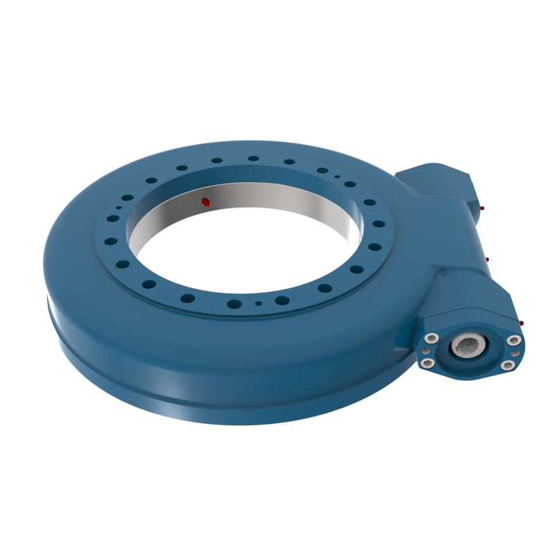
Support geometry matters just as much. A bearing ring is not a structural repair plate. If a crane pedestal, turntable, or upper frame has local deformation, cracked weld areas, damaged seating surfaces, or poor contact, the bearing can be forced to accommodate structural errors.
For severe-duty designs, the bearing arrangement should match the actual load case. For example, Three-row Roller Slewing Bearings are commonly evaluated where separate rows must carry demanding axial, radial, and moment loads. They are not automatically the best answer for every crane; design selection still depends on duty cycle, space, rotational speed, structure, and maintenance access.
Common preload mistakes that should trigger a maintenance review
- Using torque as proof of preload. Torque can be repeatable while actual clamp force varies because friction changes. Use the approved bolt condition, lubrication condition, and tightening procedure rather than assuming one torque value works in all circumstances.
- Retightening only the visibly loose bolts. A loose bolt may be a symptom of local joint movement. Review the full mounting circle, adjacent structure, and tightening records before treating the issue as isolated.
- Ignoring red-brown interface debris. This may indicate fretting, especially when found between the bearing ring and mounting face. Confirm the source before calling it normal environmental corrosion.
- Replacing a bearing without checking the support structure. A new ring installed on a damaged or uneven seat can repeat the same failure pattern. Inspect the mating faces and structural condition during bearing replacement.
- Mixing bolts or washers during field repair. Differences in length, thread engagement, surface condition, or washer style can alter joint behavior. Use the specified hardware set and maintain traceability.
- Adding extra tightening “for safety.” Excessive preload can overload bolts and distort the ring. More torque is not a substitute for verified engineering data.
These mistakes are especially relevant to cranes that work in ports, mines, forestry yards, and marine environments because cyclic loading and corrosion exposure can make mounting defects harder to detect. Environmental protection helps, but it does not replace correct joint design. A sealed slew system still needs stable mounting support.
Our product range includes bearing and drive solutions for different operating conditions, including Heavy load slewing bearing options and customized drive assemblies. Material selection can include ductile cast iron, alloy steel, stainless steel, or forged alloy steel based on load, speed, and environment.
What buyers should request from a bearing supplier and crane service team
Procurement teams should ask for information that supports the installation decision, not just the product quotation. A low initial bearing price can lose value quickly if the supplier cannot support the drawing review, mounting discussion, inspection requirements, or replacement planning.
| Request before purchase or replacement | Why it matters | Decision it supports |
|---|---|---|
| Bearing drawing and mounting interface details | Confirms hole pattern, ring orientation, gear position, and integration with the crane structure | Fit and installation planning |
| Load case and duty-cycle review | Helps separate bearing capacity needs from mounting-joint and structure concerns | Selection of bearing type and design margin |
| Bolt specification and tightening procedure | Provides a controlled method for building clamp force around the ring | Commissioning and maintenance work instructions |
| Support-surface inspection requirements | Addresses ring distortion and localized support loss before installation | Whether structure repair is needed first |
| Inspection and quality records | Creates traceability for later service analysis | Supplier qualification and maintenance documentation |
Luoyang Slewring Bearing Co., Ltd. has six production lines in an 8,000 m² manufacturing facility and an annual capacity of 100,000 sets. Standard products can be ordered from one set, while customized products have a five-set MOQ. These terms can help OEM teams validate a prototype or replacement design before larger production planning.
For evidence of supplier quality controls, buyers can also review Slew Drive Quality Control information and request relevant factory audit reports. The company provides a two-year extended quality warranty and a 48-hour technical response for confirmed support needs, with free replacement for confirmed manufacturing defects.
The practical takeaway is not that every bearing issue is a bolt-preload issue. It is that bolt preload should be treated as a controlled design and maintenance variable. When engineers verify support geometry, hardware condition, tightening sequence, and inspection records together, they have a better basis for protecting bearing raceways and extending useful service life.
Request Your Custom Slew Drive or Bearing Spec
Tell us your load, speed, and environment — receive a tailored 100–5000 mm slewing drive or slewing bearing proposal with 3D drawings within 24 hours.
 WhatsApp

 +8613903880726