


What is Worm Gear Slew Drive?
Our high-performance Worm Gear Slew Drives provide compact, robust rotational control, designed to manage high radial and axial loads with exceptional reverse self-locking safety performance. They are engineered for precision positioning and maximum reliability, essential in demanding industries such as solar tracking systems, mobile construction machinery, and industrial automation robotics. This integrated solution ensures superior torque output within a minimal footprint.
Talk to the Engineer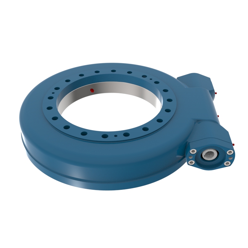
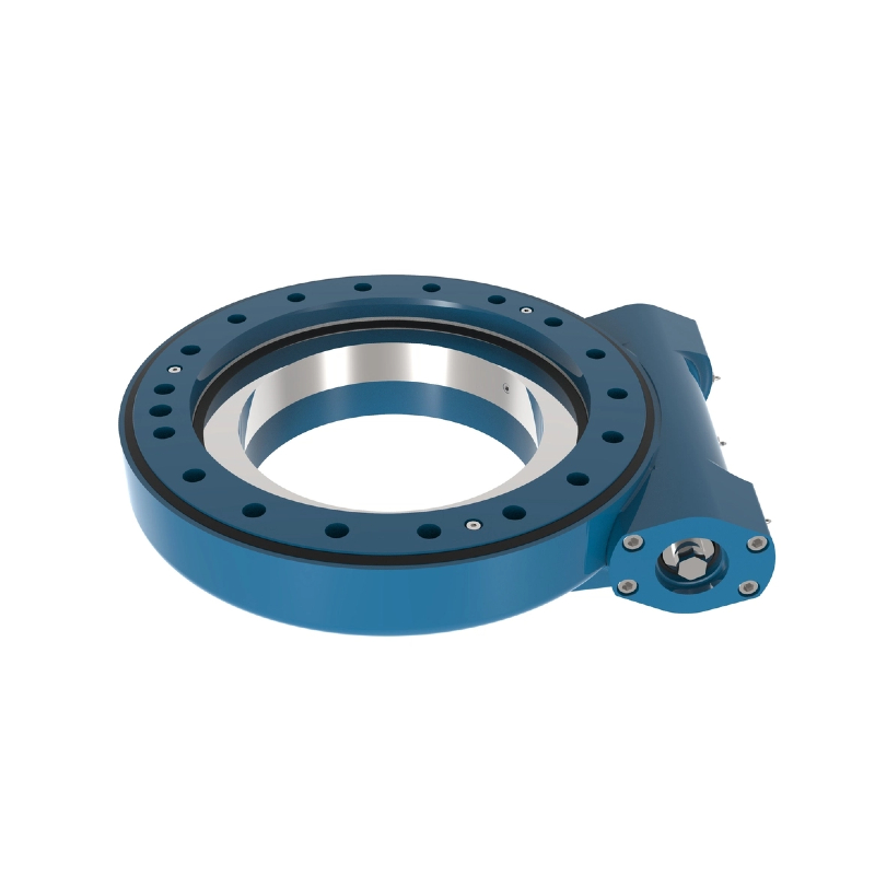
Worm Gear Drive WE17
The WE17 worm gear drive handles all load types with self-locking in a sealed, reliable design.
Read More Get A Quote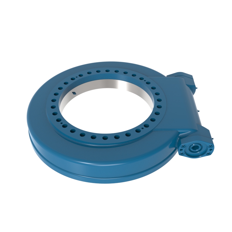
Worm Gear Drive WE19
Worm Gear Drive WE19 is an integrated drive component designed to handle axial loads, radial forces, and overturning moments, featuring a self-locking mechanism and high efficiency for various industrial applications.
Read More Get A Quote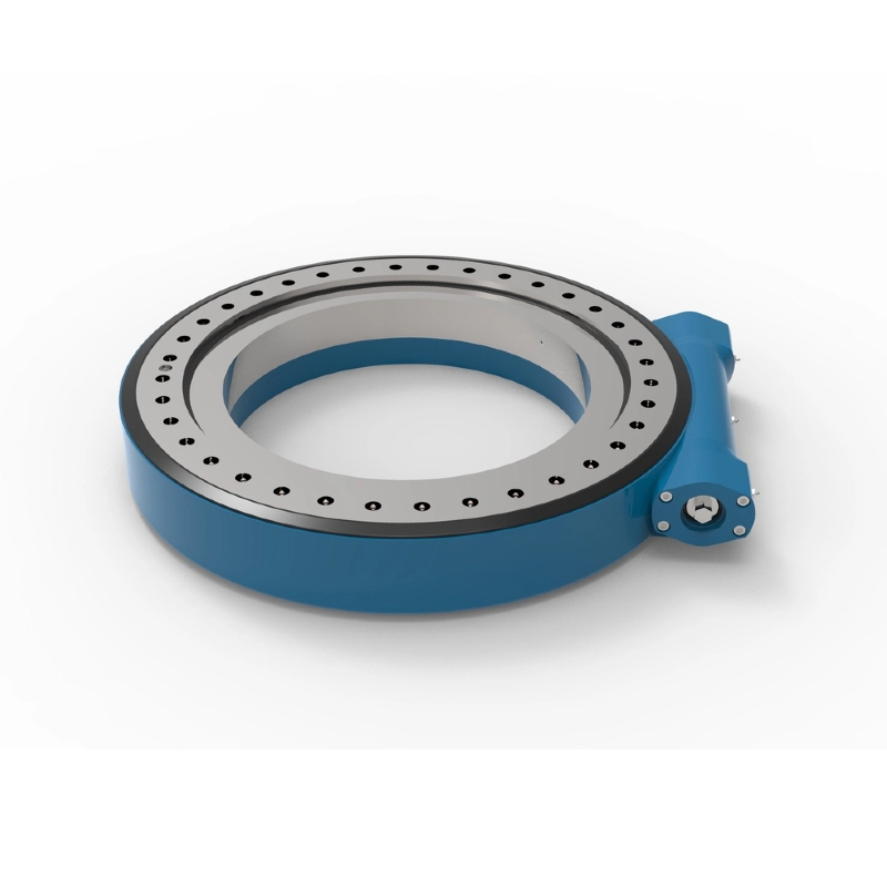
Worm Gear Drive WE25
The Worm Gear Drive WE25 is a high-precision, dustproof, and waterproof rotary drive system designed for heavy-duty applications like marine cranes and lifting equipment, offering impressive output torque, self-locking safety features, and versatility for various industrial uses.
Read More Get A Quote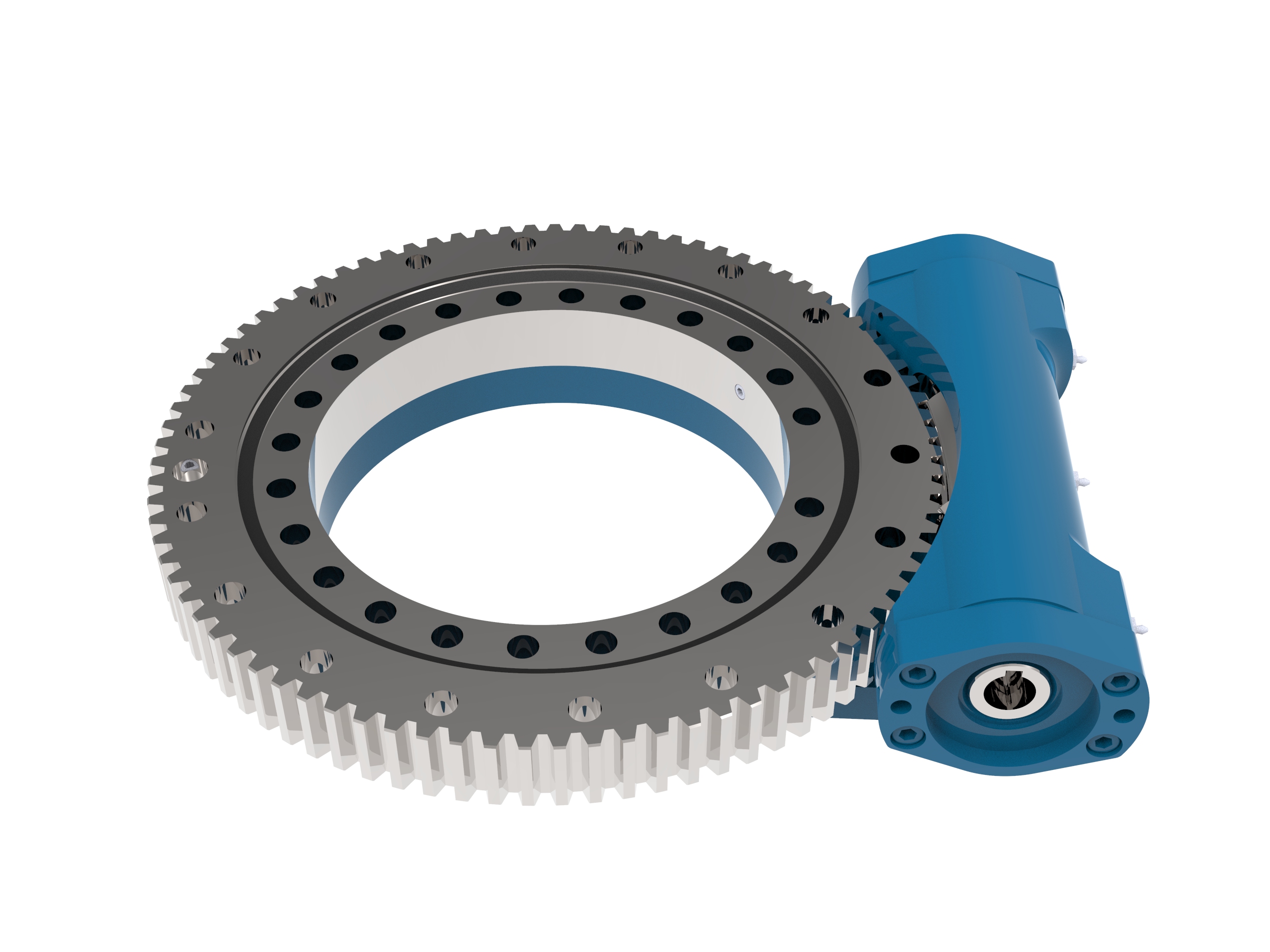
Open Housing Slew Drive S14
Open Housing Slew Drive S14 is an advanced integrated modular transmission component designed to facilitate efficient rotary motion across various applications.
Read More Get A Quote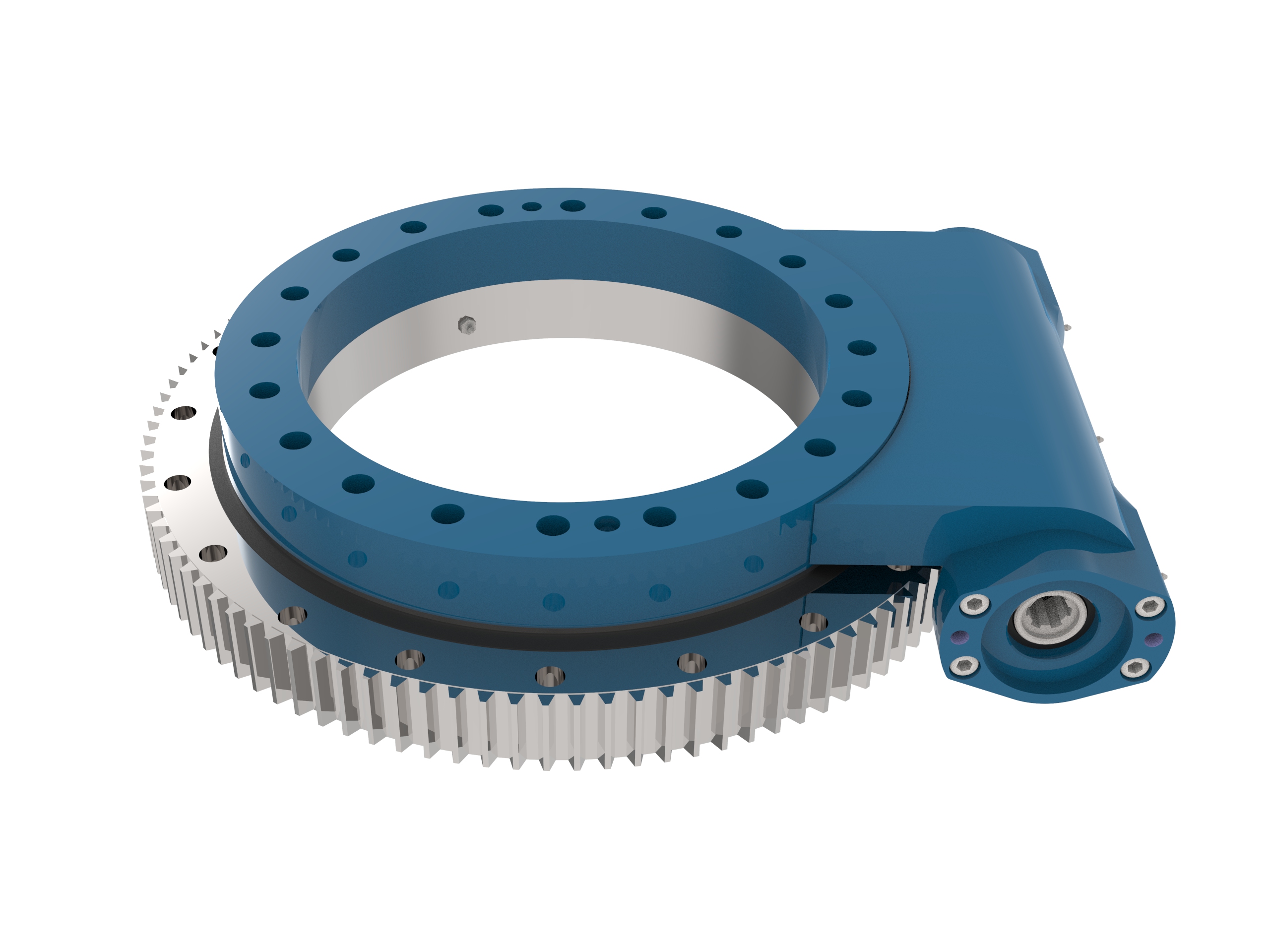
Open Housing Slew Drive S17
The Open Housing Slew Drive S17 is a versatile and lightweight integrated transmission component designed for high-performance rotary applications, featuring self-locking functionality and enhanced torque capacity, making it ideal for use in aerial work platforms, mobile cranes, and industrial machinery, with ordering facilitated through Lyra Drive, a trusted manufacturer.
Read More Get A Quote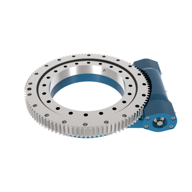
Open Housing Slew Drive S19
The Open Housing Slew Drive S19 is a lightweight, reliable rotary drive designed for various applications, featuring a self-locking mechanism, enhanced torque capabilities, and built for efficiency in industries like construction and mobile cranes.
Read More Get A Quote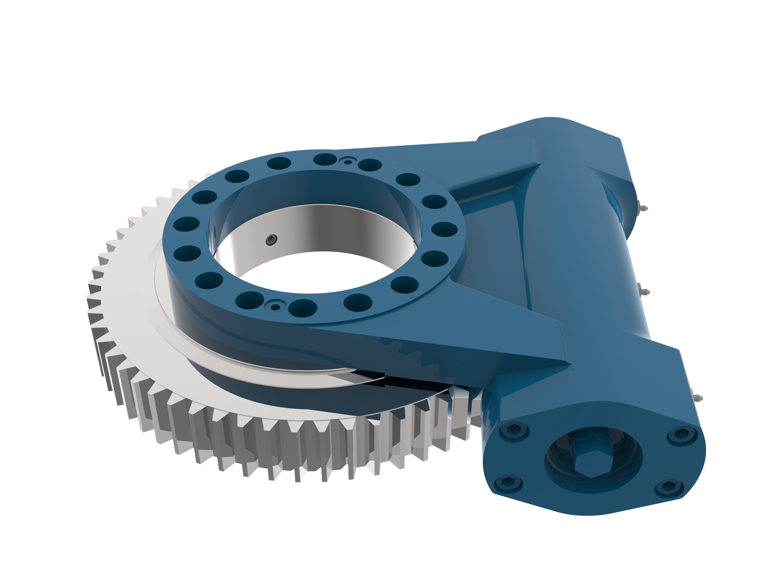
Open Housing Slew Drive S9
The Open Housing Slew Drive S9 is a lightweight, high-performance rotary drive designed for applications like aerial work platforms and cranes, featuring self-locking capabilities and enhanced torque handling, making it a reliable choice for various industrial uses.
Read More Get A Quote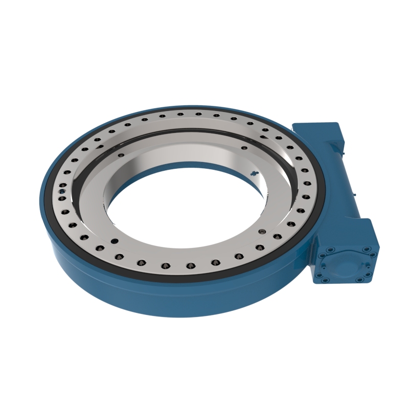
Worm Gear Drive WE21
The WE21 worm gear drive handles all load types in a sealed housing with self-locking for enhanced safety.
Read More Get A Quote
What is Worm Gear Slew Drive?
A Worm Gear Slew Drive is an integrated, heavy-duty rotation mechanism designed to transmit high torque while managing substantial multi-directional loads. The system operates on an axial worm propulsion design: an enveloping or standard worm shaft meshes with the external or internal teeth of a robust slewing ring. By transferring rotational power through perpendicular axes, it acts as a compact, drop-in speed reducer and load-bearing unit that replaces traditional multi-component gearboxes.
Key Features of Worm Gear Slew Drive
Perpendicular Axis Geometry: The output drive axis is oriented at 90 degrees relative to the input motor shaft, allowing for an incredibly shallow and compact installation footprint.
Enclosed Robust Housing: The critical internal gear meshing is fully protected within a sealed cast or ductile iron housing, preventing the ingress of dust, moisture, and industrial debris while retaining lubrication.
Multi-Load Capacity: Thanks to the integration of a high-performance slewing ring, the drive simultaneously accommodates axial forces, radial forces, and heavy tilting moment (overturning) loads.
Precision Backlash Control: Engineered with optimized gear meshing tolerances to ensure minimal backlash, providing high repeating accuracy and smooth rotational motion.
Main Types of Worm Gear Slew Drive
Single-Worm Slew Drives (Standard): Features a single worm shaft engaging the slewing ring. Ideal for cost-effective, standard industrial operations requiring reliable rotational torque and steady speeds.
Dual-Worm Slew Drives: Utilizes two worm shafts acting on the same slewing ring simultaneously. This configuration doubles the torque output and dramatically increases load capacity within the same footprint, making it perfect for high-torque environments.
Open-Housing vs. Enclosed-Housing Drives: Enclosed types are standard for outdoor or harsh factory settings where maximum environmental sealing is mandatory.
Open types are selected for sheltered installations where routine manual maintenance and visual inspection are preferred.
How Does a Worm Gear Slew Drive Work?
A worm gear slew drive works by converting high-speed, low-torque rotational input (usually from an electric or hydraulic motor) into high-torque, low-speed rotational output, while simultaneously acting as a heavy-duty structural bearing.
Here is a breakdown of the mechanical step-by-step process of how it operates:
1. Power Input via the Worm Shaft
The process begins when an external motor rotates the worm shaft (which looks like a screw with helical threads). This shaft is mounted horizontally relative to the main rotation plane, meaning the input axis is perpendicular ($90^\circ$) to the final output axis.
2. Enveloping Gear Engagement
As the worm shaft spins, its threads mesh with the teeth of the large slewing ring (gear). In high-quality drives, an enveloping worm design is used, meaning the worm shaft is hourglass-shaped to curve around the circular gear. This allows multiple gear teeth to engage at the exact same time, distributing massive loads evenly and preventing tooth breakage.
3. Axial-to-Rotational Transfer (Speed Reduction)
Because the worm shaft acts like a continuous screw, one full rotation of the shaft only advances the large slewing ring by a distance of one or two teeth. This creates a massive gear reduction ratio (often between $30:1$ and $150:1$). As speed drops drastically, the rotational torque multiplies exponentially, giving the drive the immense power needed to rotate heavy machinery.
4. Managing Simultaneous Multi-Loads
While the internal gears are turning, the integrated heavy-duty bearing assembly handles the weight. The outer or inner ring of the drive is bolted down to a stationary base, while the other ring is bolted to the moving payload (like a solar panel array or crane turret). The internal balls or rollers inside the bearing allow smooth rotation while concurrently absorbing three distinct forces:
Axial loads (straight down weight)
Radial loads (side-to-side forces)
Tilting moments (the leverage force trying to tip the system over)
The Self-Locking Phenomenon
One of the most unique operational features of a worm gear slew drive is its reverse self-locking capability.
Because the friction angle between the worm shaft threads and the gear teeth is highly acute, the worm shaft can easily drive the gear. However, the gear cannot back-drive the worm shaft. If an external force (like a massive gust of wind hitting a solar panel) tries to force the payload to rotate, the gears mechanically lock up against each other. This provides an inherent safety braking mechanism without relying on external power or secondary braking systems.
Technical Advantages of Worm Gear Slew Drive
Exceptional Reverse Self-Locking Safety: The inherent mechanical physics of the worm-and-gear mesh allows the input to drive the output, but prevents the output from back-driving the input. This ensures maximum operational safety by locking the payload securely in place when power is cut, preventing dangerous unpowered slippage under high loads.
High Torque Density: Delivers massive rotational power and high gear reduction ratios within an optimized, space-saving envelope, eliminating the need for bulky external gear trains.
Plug-and-Play Integration: Supplied as a fully assembled, pre-lubricated unit. This radically reduces engineering design hours, simplifies supply chains, and accelerates assembly times on your production line.
Low Maintenance & Extended Service Life: The combination of specialized tooth profiles, hardened steel worms, and durable sealing mechanisms ensures minimal wear, long-term grease retention, and low total cost of ownership.
Applications of Worm Gear Slew Drive
Solar Tracking Systems
Acting as the core rotational component, slew drives precisely rotate single-axis or dual-axis photovoltaic arrays to follow the sun’s trajectory, significantly maximizing solar energy capture and overall efficiency.
Mobile Construction Machinery
Widely integrated into excavator rotation mechanisms, manlifts, aerial work platforms, and truck-mounted utility cranes to provide smooth angular positioning and high load-bearing support for heavy machinery.
Industrial Automation & Robotics
Utilized in automated factory assembly lines, heavy-duty robotic arm joints, and precision indexing rotary tables where massive torque output and high positional accuracy are mandatory within a compact footprint.
Utility Cranes & Lifting Equipment
Leveraging their exceptional reverse self-locking safety performance, these drives are critical for the rotating turrets of cranes, hoists, and material handling lifters, preventing hazardous unpowered rotation under high wind or off-center loads.
Clean Energy & Wind Power
Deployed in wind turbine yaw systems and blade pitch control mechanisms, helping large turbines safely and reliably rotate the nacelle to face directly into the wind for optimal power generation.
Satellite & Antenna Positioning Systems
Engineered to control the azimuth and elevation positioning of satellite communication dishes, radar stations, and telemetry antennas, ensuring zero-slip, stable alignment even in extreme weather conditions.
How to Select Worm Gear Slew Drive?
When selecting the ideal worm gear slew drive, engineering and procurement teams should evaluate the following five core dimensions:
Load Requirements
A slew drive typically experiences forces from multiple directions simultaneously. You must evaluate:
Axial Load: The vertical gravity or thrust force acting perpendicular to the drive’s mounting surface (e.g., the dead weight of the equipment).
Radial Load: The horizontal pull or lateral force acting parallel to the drive’s mounting surface (e.g., side winds or pushing forces).
Tilting Moment: The overturning torque generated when a payload is cantilevered outwards, acting like a lever arm trying to flip the drive over.
Selection Rule: Always account for both static limits (when stopped or parked) and dynamic forces (during active rotation) to ensure the model's load curves meet your application's safety margins.
Speed and Efficiency
Speed and Duty Cycle: Worm gear slew drives are engineered for low-speed, high-torque applications. Clarify whether your system operates intermittently (e.g., solar tracking adjustments) or continuously (e.g., automation lines) so the appropriate lubrication and wear-resistant materials can be applied.
Self-Locking Safety Requirement: Determine whether your system requires exceptional reverse self-locking safety performance. If your application dictates that the payload must instantly lock in place when the motor stops to prevent dangerous unpowered back-driving, a self-locking worm gear configuration is mandatory.
Precision and Backlash
Backlash Control: Depending on your required rotational accuracy, select either a standard backlash, low-backlash, or precision-grade unit.
Positioning Accuracy: High-precision drives ensure minimal rotational "play" or clearance, which is essential for critical alignment applications like radar positioning and robotic arm joints.
Environment & Space
Enclosed Housing: If your equipment operates outdoors, in high-dust environments (such as mining or construction sites), or under wet conditions, select a fully enclosed housing with high ingress protection to seal out contaminants and retain grease.
Open Housing: If the unit is installed inside a clean, sheltered factory enclosure where visual gear inspection is preferred and routine manual maintenance is simple, an open structure may be utilized.
Space Optimization: The perpendicular geometry of the worm gear design allows for an incredibly compact installation footprint, making it ideal for applications with strict spatial limitations.
Material & Cost
Corrosion Resistance: For marine environments, coastal regions, or chemical processing plants, specify specialized surface treatments such as customized painting, zinc plating, or stainless steel components to extend service life.
Cost Efficiency: Choosing an integrated, ready-to-install slew drive eliminates the need for complex, multi-component gearboxes, significantly reducing upfront engineering design hours, simplifying supply chains, and lowering long-term maintenance costs.
Worm Gear Slew Drive Installation and Operation Manual
Important Notice: Read this manual thoroughly before installing or operating the Worm Gear Slew Drive. Contains vital safety and operational information. Installation must be performed by certified technicians.
Transportation and Handling: Transport in original packaging with proper orientation markings facing upward. Use certified lifting equipment with minimum 4 attachment points. Never lift using motor shafts or external components. Maintain ambient temperature between -20°C to 50°C during transit.
Storage Guidelines: Indoor storage preferred in climate-controlled environment. Relative humidity must not exceed 70%. Rotate drive 90° every 3 months if stored long-term. Preservative coating effective for 12 months in unopened packaging.
Checklist & Surface Prep: Verify drive model matches specifications and inspect for shipping damage. Confirm all mounting surfaces within 0.1mm flatness tolerance. Degrease using isopropyl alcohol and remove oxidation. Apply thin layer of nickel-based anti-seize compound.
Fastener Specifications: Metric coarse thread series (ISO 898-1 compliant). Minimum property class 10.9 for all structural connections. Thread engagement = 1.5 × nominal diameter (minimum). Prevailing torque locknuts required for all vertical applications.
Recommended Installation Torques (Dry)
| Bolt Size | Initial Torque (Nm) | Final Torque (Nm) | Angle Tightening (°) |
|---|---|---|---|
| M12 | 60 | 120 | 90 |
| M16 | 150 | 300 | 120 |
| M20 | 300 | 600 | 180 |
| M24 | 520 | 1040 | 270 |
Tightening Pattern: Follow crisscross sequence starting from center bolts moving outward.
Lubrication Requirements: Primary gear uses Mobil SHC 460 (or equivalent synthetic). Bearings use Kluber Staburags NBU 30/600. Seals use Molykote 111 silicone paste. Gear chamber fill quantity is 80% of free volume; Bearing cavities is 30-40% fill ratio.
Maintenance Schedule (Standard Operating Conditions)
| Parameter | Interval | Action Required |
|---|---|---|
| Visual Inspection | Weekly | Check for leaks, unusual noise |
| Lubricant Analysis | Quarterly | Send sample to lab |
| Backlash Measurement | Biannually | Record wear patterns |
| Complete Overhaul | 20,000 hours | Full disassembly inspection |
For severe service conditions (continuous operation >16hr/day, high shock loading, or marine environments), reduce all intervals by 50%.
Break-in Procedure (First 100 Hours): Limit to 50% rated load. Operate through full rotation every 2 hours. Monitor temperature (≤85°C surface temp). Check lubrication after first 24 hours.
Troubleshooting Guide
| Symptom | Likely Cause | Corrective Action |
|---|---|---|
| Excessive noise | Lubrication failure | Immediate relubrication |
| Overheating | Misalignment | Laser alignment check |
| Irregular motion | Backlash increase | Adjust preload or replace gear |
| Oil leakage | Seal degradation | Replace all shaft seals |
Safety Protocols & Warnings
⚠️ Lockout/Tagout procedures mandatory for maintenance.
⚠️ Personal protective equipment required: Cut-resistant gloves, safety goggles, steel-toe footwear.
⚠️ Never exceed maximum rated parameters: 120% peak torque (intermittent), 100% continuous torque, 15 rpm maximum input speed.
Can't find a slew drive that fits your needs? Our team of engineers can design a slew drive unique to your application. To learn more about our products, including slew drive price, request a quote or contact us directly.