


The installation methods of the spur gear slew drives
What is Spur Gear Slew Drive?
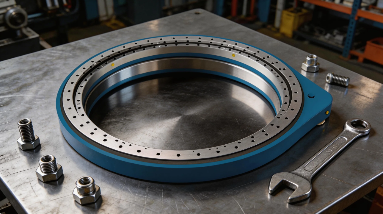
A spur gear slew drive is a compact rotary bearing mechanism that integrates a slew bearing (slewing ring) with a spur gear system. Unlike worm gear drives, the spur gear design offers zero backlash potential and high rotational speeds. It is engineered to handle simultaneous axial, radial, and tilting moment loads, making it the preferred choice for applications requiring precise positioning and high duty cycles.
How Does a Spur Gear Slew Drive Work?
The operating principle is based on direct gear meshing. A pinion (input gear), connected to a motor, engages directly with the spur gear teeth cut into the race of the slew bearing. As the pinion rotates, it travels along the gear teeth, causing the bearing race to rotate relative to the fixed housing. This direct drive mechanism provides high positional accuracy and mechanical efficiency, typically exceeding 90%.
Applications of Spur Gear Slew Drive
Due to its precision and speed capabilities, the spur gear slew drive is widely used in:
Solar Tracking Systems: Single-axis and dual-axis trackers requiring frequent, minute-by-minute adjustments.
Medical Equipment: CT scanners and radiotherapy tables where silent, smooth rotation is mandatory.
Material Handling: Rotary tables, manipulators, and automated lifts.
Defense & Aerospace: Radar antenna platforms and turret drives.
Spur Gear Slew Drive Installation Methods
Based on standard industry practice and the reference technical documentation, there are three primary installation methods for spur gear slew drives. Each method is defined by the shaft configuration and support structure. The selection of the appropriate method depends on the application requirements, available space, and load characteristics.
A. Fixed Installation with Solid Shaft
This is the most widely adopted installation method for spur gear slew drives.
Connection Type: The solid output shaft of the slew drive is connected to the driven machinery (metallurgical equipment, solar trackers, or material handling systems) via couplings, sprockets, gears, or pulleys.
Foundation Fixing: The slew drive housing is firmly secured to the structure using anchor bolts mounted through the drive feet. The foundation must be solid, rigid, and vibration-free.
Large Drive Adjustment: For large-scale spur gear slew drives, threaded holes are machined into the housing feet. Adjusting bolts are used to fine-tune the installation position precisely before final tightening.
Luffing Mechanism Locking: When the slew drive is used in luffing mechanisms (e.g., crane booms or lifting applications), taper pins must be used for locking after positioning. This prevents any movement or shifting during operation.
Typical Applications: Standard rotary tables, general industrial positioning, crane slewing, and solar tracking foundations.
B. Single-Point Floating Installation of Hollow Shaft
This method utilizes a hollow output shaft and is designed to eliminate additional bending forces on the transmission shaft.
Connection Type: The hollow output shaft is connected to the working machine’s transmission shaft via an expansion sleeve (shrink disc). This provides a backlash-free, keyless connection.
Drive Assembly Support: The entire drive train—including the motor, coupling, brake, and spur gear slew drive—is mounted on a support base. This base is then supported by a spherical hinge or bearing.
Principle of Operation: The bearing point of the spherical hinge is deliberately positioned offset from the center of gravity of the transmission device by a calculated distance.
Moment Balancing: During operation, the bending moment caused by this support point eccentricity counterbalances the bending moment generated by the drive load. As a result, the transmission shaft is subjected to zero additional bending forces in theory.
Advantages: Eliminates external bending moments, reduces shaft fatigue, extends bearing life.
Typical Applications: Heavy-duty conveyors, large mining equipment, and applications where the drive train cannot be perfectly aligned.
C. Hollow Shaft Suspension Installation
This method is a space-saving, weight-reducing solution where the slew drive is suspended directly on the machinery shaft.
Connection Type: The hollow output shaft of the spur gear slew drive is connected directly to the metallurgical machinery shaft using an expansion sleeve. No separate coupling or baseplate is required at the output side.
Support Mechanism: The drive is supported by two points:
The output shaft connection (providing the primary radial support).
A torsion rod or torque arm (preventing the drive housing from rotating).
Key Characteristics:
Simplified Structure: Eliminates the need for a separate bearing housing or heavy support base at the output end.
Space Efficient: Significantly reduces the overall footprint of the drive system.
Weight Reduction: Lowers the total machine weight, which is critical for mobile or suspended applications.
Power Direction: This method is particularly suitable for transmission devices that deliver power from a vertical direction.
Advantages: Compact design, lower installation cost, reduced machine weight, ideal for vertical power transmission.
Typical Applications: Agitators, vertical mixers, suspended crane drives, and marine deck machinery.
Summary of Installation Methods:
| Method | Shaft Type | Support Structure | Key Feature |
|---|---|---|---|
| Fixed Installation | Solid Shaft | Anchor bolts on rigid foundation | Traditional, most common, taper pin locking for luffing |
| Single-Point Floating | Hollow Shaft | Spherical hinge + support base | Moment balancing, zero additional bending force |
| Hollow Shaft Suspension | Hollow Shaft | Output shaft + torsion rod | Space-saving, lightweight, vertical power transmission |
General Installation Sequence:
Spur gear slew drive installation is a precision task with high technical requirements. Regardless of the method selected, the following general sequence must be strictly observed:
Equipment Leveling and Alignment
Cleaning and Assembly
Adjustment and Trial Operation
All installation work must be carried out in strict compliance with the operating procedures and design data provided by the manufacturer. Proper method selection and execution directly determine the service life, efficiency, and safety of the spur gear slew drive
Critical Installation Precautions & Common Mistakes
Avoiding these errors is vital for warranty validity and operational safety.
A. Lubrication: Oil Grade, Quantity, and Initial Change
Lubrication is the lifeblood of the gear drive. Poor lubrication generates excessive heat and drastically reduces load capacity.
Oil Grade Selection:
Ambient Temperature (0~35°C) or Circulating Oil: Use Medium-load Industrial Gear Oil 220#.
Ambient Temperature (35~50°C): Use Medium-load Industrial Gear Oil 320#.
Oil Quantity: The amount of oil must be exact. Each slew drive has a nameplate specifying the correct grade and quantity. Do not guess.
Oil Level: Use the oil sight glass/mirror on the side of the drive. The oil level must reach between the upper and lower marks of the sight glass. Overfilling causes churning losses and overheating; underfilling causes starvation and seizure.
Initial Oil Change: The lubricating oil must be replaced after the first 400 hours of operation. This removes initial wear particles and break-in debris.
B. Lubrication Method Selection
Standard Conditions: For standard power ratings, oil bath lubrication and natural cooling are sufficient.
High Power/High Heat: For high-power slew drives or applications with insufficient thermal dissipation, you must use pressure circulating oil lubrication or add an auxiliary cooling device.
C. Bolt and Fastener Safety
Bolt Grade: Only use the specified high-strength bolt grade (typically 10.9 or 12.9). Do not substitute with lower-grade hardware.
Torquing Sequence: Always tighten bolts in 3-4 incremental steps following a cross-pattern.
D. Structural Rigidity
Mounting on thin, flexible structures is a common mistake. The support structure must be stiff enough to prevent the drive housing from "breathing" under load, which leads to misalignment and rapid tooth wear.
How to Correctly Install a Spur Gear Slew Drive
Follow this summarized verification checklist for a perfect installation:
Clean all mating surfaces and shafts.
Inspect surfaces for flatness and bolts for correct grade.
Lift the drive carefully, protecting the seals.
Position the drive, ensuring flush contact.
Align shafts to within φ0.1mm coaxiality and maintain the 2-8mm end gap.
Torque bolts in a cross pattern to the specified value.
Lubricate with the correct oil grade to the proper sight glass level.
Test rotate by hand to ensure smooth motion.
Change oil after the first 400 hours of operation.
LyraDrive: Customised Spur Gear Slew Drive Solutions
At LyraDrive, we specialize in the design and manufacture of high-precision slew drives and slew bearings. While this guide covers standard installation best practices, we know that every machine is unique.
We offer fully customised spur gear slew drive solutions tailored to your specific load, speed, and mounting interface requirements. Our engineering team can modify gear ratios, housing dimensions, and sealing options to fit your existing design perfectly.
Importantly, LyraDrive provides more than just components. When you choose us, you gain direct access to our application engineers for professional installation guidance and method recommendations. Whether you need a detailed installation drawing review or advice on a complex mounting scenario, we are here to ensure your drive performs reliably from day one.
FAQ of Spur Gear Slew Drive Installation
Q1: My mounting plate is painted. Can I install the slew drive directly on the paint?
A: No. Paint is a soft film that creeps under high clamping loads, causing bolts to lose preload. Always mount on clean, bare, machined metal.
Q2: How do I know if I have the right amount of oil?
A: Check the oil sight glass on the side of the drive. The oil level should be visible in the middle of the glass—between the upper and lower indicator marks.
Q3: The drive was smooth on the bench, but now it is hard to turn. Why?
A: This usually indicates the mounting surface is not flat. Tightening the bolts has distorted the drive housing. You must remove the unit, check the flatness of your structure, and use shims to correct it.
Q4: Can I use any 220# gear oil?
A: You must use Medium-load Industrial Gear Oil as specified. Standard automotive gear oils may lack the required extreme pressure (EP) additives for slew drive applications.
Q5: Why is the first oil change at 400 hours important?
A: During the first 400 hours, the gears and bearings undergo a "break-in" period. Small wear particles are generated. Changing the oil removes this abrasive debris and protects the drive for its long-term service life
Q5: Why is the first oil change at 400 hours important?
A: During the first 400 hours, the gears and bearings undergo a "break-in" period. Small wear particles are generated. Changing the oil removes this abrasive debris and protects the drive for its long-term service life