



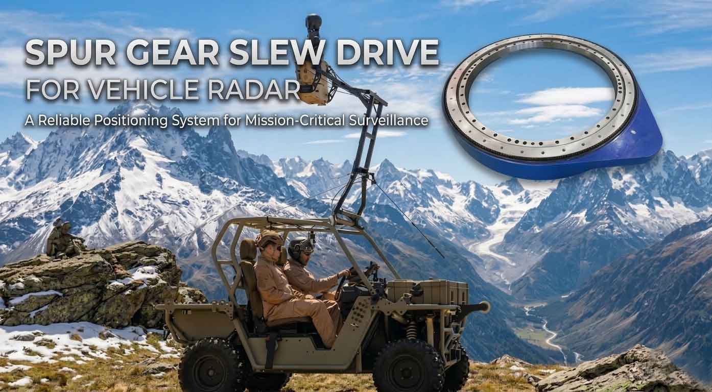
Spur Gear Slew Drive For Vehicle Radar
What is a Spur Gear Slew Drive For Vehicle Radar?
A spur gear slew drive is a compact rotational device that enables precise 360° azimuth movement for radar units mounted on vehicles. It consists of a small spur pinion driving a large ring gear, integrated with a heavy-duty bearing and sealing system.
In vehicle radar applications, the slew drive is mounted between the vehicle structure (roof, turret, or platform) and the radar antenna assembly. Its primary role is to rotate the radar continuously or in discrete steps, allowing the sensor to scan the full surrounding environment. Common applications include military surveillance radars, autonomous mining truck obstacle detection, port anti-collision systems, and mobile weather radar vans.
Key Components of a Spur Gear Slew Drive For Vehicle Radar
Understanding the internal architecture of a spur gear slew drive helps explain its performance characteristics. While designs vary by manufacturer and application, the following core components are present in virtually all spur gear slew drives used for vehicle radar systems.
1. Spur Pinion (Input Gear)
The pinion is the small, driven gear that receives torque from the motor (electric or hydraulic). It features straight-cut teeth and is typically made from case-hardened alloy steel (e.g., 42CrMo4) to resist wear under cyclic loading. The pinion’s tooth profile is precision-ground to achieve the low backlash required for radar positioning accuracy.
2. Spur Ring Gear (Output Gear)
The ring gear is the large-diameter internal or external gear that meshes with the pinion. In most vehicle radar applications, an internal ring gear is used to save axial space and protect the gear teeth from debris. The ring gear is usually integrated into the rotating housing of the slew drive. Its pitch diameter determines the drive’s torque multiplication ratio — larger ring gears provide higher torque at lower output speeds.
3. Housing (Fixed and Rotating Sections)
The slew drive features two primary housing sections: a fixed outer housing that bolts to the vehicle structure, and a rotating inner ring that supports the radar antenna. Both sections are typically made from high-strength ductile iron (e.g., GGG-40) or forged steel for rigidity and impact resistance.
4. Axial-Radial Bearing
Unlike simple gearboxes, a slew drive must support significant axial (thrust) and radial loads while also resisting tilting moments caused by wind, vehicle motion, and antenna inertia. A large-diameter single-row or double-row ball bearing is integrated directly into the housing. In high-precision radar applications, a crossed-roller bearing may be used for greater moment rigidity and lower runout.
5. Sealing System
Vehicle radar operates in harsh environments: dust, mud, road salt, high-pressure washdowns, and temperature extremes. Heavy-duty dual-lip nitrile or silicone seals are installed at all dynamic interfaces to prevent contaminant ingress and retain grease lubrication. Top-tier designs achieve IP65 or even IP66 ratings.
6. Lubrication Ports and Channels
Proper lubrication is critical for gear life and backlash stability. Most spur gear slew drives include grease fittings (Zerk fittings) and internal channels to direct lubricant to the pinion-ring gear mesh and the bearing raceways. For extreme cold climates, synthetic low-temperature greases (e.g., Mobilith SHC 100) are specified.
7. Optional Feedback Sensors
For closed-loop radar positioning, the slew drive may integrate an encoder, resolver, or potentiometer on the input shaft or output flange. These sensors provide real-time angular position data to the vehicle’s radar control system, enabling precise beam steering.
8. Brake (Optional but Common)
While not strictly required for scanning operation, many vehicle radar slew drives include a spring-applied, electrically released parking brake to prevent unintended rotation during vehicle transport or when the radar is powered off.
How a Spur Gear Slew Drive Works For Vehicle Radar?
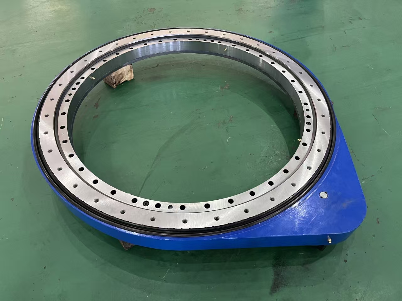
The operational principle of a spur gear slew drive is straightforward, but several engineering details are worth examining to appreciate why this configuration works so well for vehicle radar.
Step 1: Motor Input
An electric motor (typically 12V, 24V, or 48V DC for vehicle compatibility) or a hydraulic motor delivers rotational torque to the spur pinion. The motor speed is controlled by the radar system’s motion controller, which may command continuous rotation (for scanning), step rotation (for sector searches), or precise indexing (for target tracking).
Step 2: Gear Reduction and Torque Multiplication
As the small pinion rotates, it drives the large ring gear. The gear ratio is calculated as:
Ratio = (Number of teeth on ring gear) / (Number of teeth on pinion)
For a typical vehicle radar slew drive, ratios range from 50:1 to 200:1. This reduction simultaneously multiplies torque (enabling the drive to rotate a heavy antenna despite a small motor) and reduces output speed (ensuring stable, controllable scanning rates).
Step 3: Load Support Through Integrated Bearing
Unlike a simple gear train, the slew drive’s integrated bearing carries all external loads. As the vehicle drives over bumps or encounters crosswinds, axial forces (vertical), radial forces (horizontal), and moment loads (tilting) are transferred directly from the radar antenna into the bearing. The pinion and ring gear mesh sees only the driving torque — not the external loads — which protects the gear teeth from overstress.
Step 4: Backlash Management
Backlash — the small gap between mating gear teeth — is critical for radar applications. Excessive backlash causes angular lag and position uncertainty. Spur gear slew drives achieve low backlash (typically 0.05° to 0.15° or 3–9 arcminutes) through precision grinding of gear teeth and adjustable preloading of the bearing. Some high-end designs incorporate split pinions or eccentric adjustment to actively eliminate backlash.
Step 5: Position Feedback and Control
The encoder or resolver mounted on the slew drive sends continuous position data to the radar controller. When the controller commands a specific azimuth angle (e.g., “rotate to 137°”), it compares the actual position to the target and adjusts motor current accordingly. This closed-loop control enables radar systems to track moving targets with high accuracy.
Step 6: Braking and Hold
When the radar reaches its target position (or when the vehicle is powered off), the spring-applied brake engages to hold the output flange against any external disturbance torque. This prevents “windmilling” — unwanted rotation caused by wind or vehicle vibration — which would degrade radar calibration.
In continuous scanning mode, the brake remains disengaged, and the motor reverses direction periodically to avoid cable wrap. Modern systems use slip rings or rotary joints to pass power and data across the rotating interface, allowing unlimited continuous rotation.
Advantages of Spur Gear Slew Drive vs. Worm Gear Slew Drive For Vehicle Radar
When selecting a slew drive for vehicle radar, the most common alternative is the worm gear slew drive. Understanding the comparative advantages of spur gear designs helps engineers make informed decisions.
Higher Rotational Speed
Worm gear drives rely on sliding contact between the worm and wheel, which generates significant friction and heat at speeds above 10–15 rpm. Spur gear drives, using rolling contact, can operate at 30–50 rpm or higher without overheating. This allows vehicle radar systems to complete a full 360° scan in under 2 seconds — critical for threat detection or obstacle mapping.
Higher Efficiency
Worm gear efficiency typically ranges from 50% to 70% due to sliding friction. Spur gear efficiency runs from 90% to 95%. For battery-powered electric vehicles (e.g., autonomous patrol vehicles or electric mining trucks), this efficiency difference translates directly into longer operating range or smaller battery requirements.
Bidirectional Operation with Equal Performance
Worm gears are inherently asymmetrical: backdriving (rotating the output to turn the input) is inefficient and often impossible without a separate release mechanism. Spur gears are fully reversible — the motor can drive the radar, and external forces (like manual alignment) can backdrive the system without damage. This simplifies maintenance and manual override.
Lower Backlash at Comparable Cost
Precision worm gears can achieve very low backlash (1–3 arcminutes), but this requires expensive dual-lead worms or split-worm designs. Spur gear slew drives achieve similarly low backlash (3–9 arcminutes) at lower manufacturing cost for the same torque rating. For radar applications where 5–10 arcminutes of accuracy is sufficient, spur gears offer a better cost-performance balance.
Better Heat Dissipation
Worm gear drives concentrate heat at the worm-wheel interface, requiring oil cooling or oversized housings for high-duty-cycle applications. Spur gears dissipate heat across a larger gear mesh area and can often run without forced cooling — even in continuous scanning radar systems.
Note: Worm gears remain superior when self-locking (the ability to hold position without a brake) is required. However, most vehicle radar systems already include a separate parking brake, making self-locking redundant. Therefore, spur gear slew drives are increasingly the preferred choice for new vehicle radar designs.
Typical Radar Types on Vehicles That Use Spur Gear Slew Drives
The term “vehicle radar” covers several distinct sensor types, each with different rotational requirements. Spur gear slew drives are found on the following common vehicle-mounted radar categories:
Mechanical Scanning Radar – The traditional rotating antenna design. A spur gear slew drive rotates the entire horn or reflector assembly continuously. Used in marine navigation radars on port vehicles and older military ground surveillance platforms.
Phased Array Radar with Rotating Mount – Although phased array radars electronically steer their beam, many are still mounted on a rotating slew drive to provide a hemispherical scan volume. This hybrid approach reduces the number of active elements needed. Common on mobile air defense vehicles.
Imaging Radar (4D / Doppler) – Next-generation automotive and off-highway radars use rotating spur gear drives to physically point high-gain antennas for long-range detection. Autonomous trucking companies frequently specify custom slew drives for their perception stacks.
Tracking Radar – Instead of continuous scanning, tracking radars follow a single target. The slew drive must execute precise, small-angle movements (e.g., 0.1° steps) at variable speeds. Low backlash and high stiffness are paramount here.
Calibration & Testing Radar – Vehicle radar calibration systems use spur gear slew drives to position reference targets during production line or service center testing. Accuracy requirements can reach P2 precision grade.
Multi-Sensor Turrets – Some vehicle platforms integrate radar with cameras, LIDAR, and IR sensors on a common rotating turret. The spur gear slew drive must support the combined weight and inertia of all sensors while maintaining alignment.
Selection Criteria When Choosing a Spur Gear Slew Drive for Vehicle Radar
Selecting the correct spur gear slew drive requires evaluating eight technical parameters:
| Parameter | Why It Matters | Typical Vehicle Radar Value |
|---|---|---|
| Output torque (static & dynamic) | Must accelerate the radar antenna and resist wind/vibration | 500–5,000 Nm |
| Backlash | Affects angular positioning error | 3–15 arcminutes |
| Axial load capacity | Supports antenna weight + vertical vibration | 10–50 kN |
| Radial load capacity | Resists side loads from vehicle cornering | 5–25 kN |
| Tilting moment capacity | Prevents wobble from antenna overhang | 10–100 kNm |
| IP rating | Protects against dust, washdown, salt | IP65 or IP66 |
| Operating temperature range | Vehicle operation from arctic to desert | -40°C to +80°C |
| Feedback sensor option | Enables closed-loop radar control | Encoder (absolute or incremental) |
Additionally, the mounting interface must match the vehicle’s bolt pattern and the radar antenna’s pilot diameter. LyraDrive specializes in adapting these interfaces to customer specifications.
Maintenance & Troubleshooting Tips for Vehicle Radar Slew Drives
Field experience shows that most spur gear slew drive failures in vehicle radar applications result from lubrication neglect or seal damage. Follow these guidelines:
Lubrication Schedule
Grease every 2,000 operating hours or annually, whichever comes first.
Use NLGI #2 lithium-complex grease for temperate climates; switch to synthetic low-temperature grease (e.g., Klüberplex BEM 34-132) for below -20°C.
Apply grease while rotating the drive slowly to ensure even distribution.
Backlash Monitoring
Annually measure backlash by clamping the output flange and applying torque to the input.
If backlash exceeds 0.2° (12 arcminutes) , inspect the pinion and ring gear teeth for wear. Replace both gears as a matched set.
Seal Inspection
Before each field deployment, check for grease leakage around the shaft seals.
Leaking seals allow contaminants in — replace immediately. Seal life is typically 5–7 years in normal use.
Bolt Torque Verification
After the first 100 hours of operation, re-torque all mounting bolts to the specified value (typically 70–80% of yield).
Repeat annually or after any hard impact event.
Storage Procedure
If the vehicle will be parked for over one month, manually rotate the radar 90° every 30 days to prevent bearing brinelling (false brinelling damage).
For long-term storage (>6 months), apply preservative grease and cover the slew drive with a breathable dust cover.
Troubleshooting Quick Reference
| Symptom | Likely Cause | Fix |
|---|---|---|
| Grinding noise during rotation | Contaminated grease or tooth wear | Flush and regrease; inspect gears |
| Radar position drifts after stop | Brake not engaging | Check brake power supply and solenoid |
| High motor current | Bearing preload too high or lubrication dried | Reduce preload; relubricate |
| Uneven rotation (cogging) | Pinion misalignment or damaged bearing | Realign motor coupling; replace bearing |
LyraDrive: Custom Spur Gear Slew Drive Supplier for Vehicle Radar Systems
LyraDrive is a professional one-stop slewing device manufacturer specializing in the design, development, customized production, sales, and service of slew drives and slewing bearings. Our product portfolio includes spur gear slew drives, and we provide tailored solutions specifically engineered for vehicle radar systems.
Why LyraDrive for Your Vehicle Radar Project?
Complete Customization
Every vehicle radar platform has unique requirements: mounting interface, torque output, backlash control, IP rating, and motor integration. LyraDrive works with you from concept to delivery — just submit your requirements via email, and our team will provide a complete design including 3D files for validation.Wide Size & Precision Range
Our customizable spur gear slew drives cover a size range from 100 mm to 5000 mm, with precision grades reaching P0, P6, P5, P4, and even P2 — ensuring the angular accuracy your radar needs for reliable target tracking.Designed for Harsh Vehicle Environments
Whether your radar operates on dusty construction sites, vibration-heavy off-road vehicles, or corrosion-prone marine platforms, LyraDrive delivers. We tailor sealing, lubrication, and materials to match your specific operating conditions — dust-proof, corrosion-resistant, or even medical-grade clean environments.Beyond Spur Gear: A Full Portfolio
While our spur gear slew drives are ideal for high-speed, low-backlash radar scanning, LyraDrive also offers worm slew drives and worm gear drives for applications requiring self-locking or higher reduction ratios. This means you get the right drive technology — not just what we happen to stock.
From Requirement to 3D Model — Fast
LyraDrive doesn’t believe in off-the-shelf compromises. We believe in engineering partnerships.
Send us your vehicle radar specs (load, speed, mounting pattern, environmental rating, motor type), and we’ll respond with a custom spur gear slew drive proposal and 3D drawings.
👉 Need a reliable, custom spur gear slew drive for your vehicle radar system? Contact LyraDrive today — your rotation, our precision.
FAQ About Spur Gear Slew Drive for Vehicle Radar Systems
Q1: Can a spur gear slew drive handle the vibration from off-road vehicles?
Yes. Spur gear slew drives with crossed-roller bearings and case-hardened gears are specifically designed for high-vibration environments. However, you must specify the expected vibration spectrum (frequency and acceleration) so the manufacturer can select appropriate bearing preload and internal clearances. LyraDrive routinely supplies units for military and mining vehicles with MIL-STD-810 vibration compliance.
Q2: What backlash level is typical for vehicle radar applications?
For most mechanical scanning radars, 5–10 arcminutes (0.08°–0.17°) is acceptable. For precision tracking radars or phased array calibration systems, specify 3 arcminutes or less. Below 3 arcminutes requires precision-ground gears and careful assembly — achievable but at higher cost. LyraDrive offers P4 and P2 precision grades for sub-3-arcminute backlash.
Q3: Do I need a separate brake for the slew drive?
If your radar system must maintain position when power is removed (e.g., to avoid spinning during vehicle transport), yes. Spur gear drives are not self-locking. LyraDrive can integrate a spring-applied, electrically released parking brake directly into the slew drive housing, saving space and simplifying wiring. For continuous scanning applications where the radar always returns to a park position before shutdown, a brake may be optional.
Q4: Can LyraDrive provide custom mounting interfaces for my radar platform?
Absolutely. This is one of our core competencies. Provide your radar antenna’s bolt circle diameter, pilot diameter, and thread specifications, and we will machine the output flange accordingly. Similarly, we can adapt the fixed housing to your vehicle’s roof or turret mounting pattern — no adapter plates required. Send your mechanical drawings or a simple sketch to our engineering team, and we will respond with a 3D model within 48 hours
 WhatsApp
 sales@lyradrive.com
 +8613903880726