



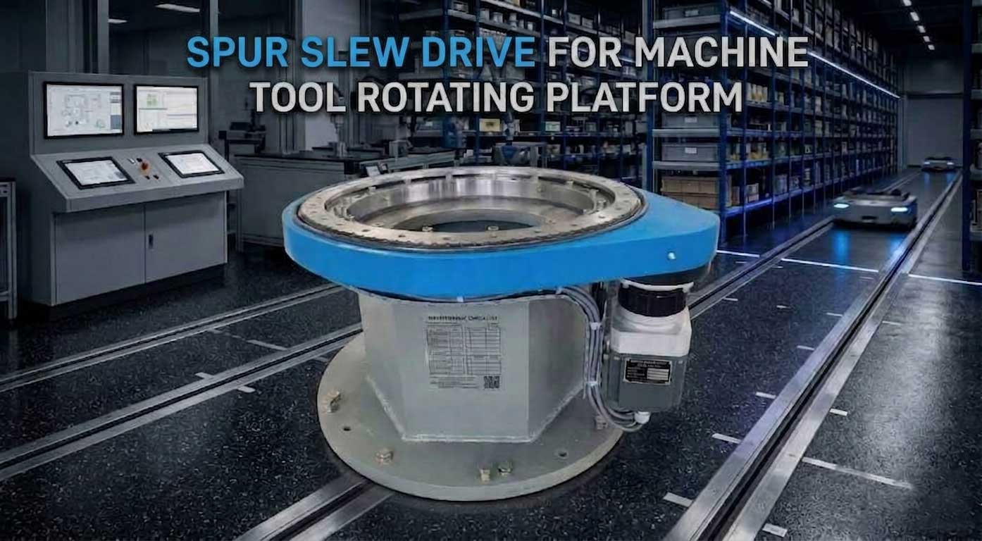
Spur Slew Drive For Machine Tool Rotating Platform
What Is Spur Slew Drive for Machine Tool Rotating Platforms
A spur slew drive is a precision-engineered rotary actuation device that integrates a spur gear arrangement, a heavy-duty bearing, and a robust housing into a single compact assembly. When applied to a machine tool rotating platform, this drive enables controlled, repeatable rotary motion for critical components such as CNC rotary tables, indexing tables, trunnion tables, and pallet changers. Unlike other slew drive configurations, the spur gear design uses straight-cut teeth with axes parallel to each other, allowing efficient power transmission from the input pinion to the large-diameter slewing ring. The bearing is typically a four-point contact ball bearing or crossed roller bearing, providing high axial and radial load capacity while maintaining low rotational friction. This combination of gearing and bearing makes the spur slew drive particularly well-suited for machine tool applications where stiffness, precision, and dynamic response are paramount.
Key Features of Spur Slew Drive
The spur slew drive offers several distinctive features that make it ideal for machine tool rotating platforms:
Straight tooth geometry – The teeth are cut parallel to the axis of rotation, allowing simultaneous line contact across the entire tooth width. This geometry creates a smooth, predictable engagement pattern that distributes load evenly and minimizes localized stress concentrations.
High rigidity – The large-diameter bearing integrated directly into the drive housing supports heavy cutting forces, workpiece loads, and fixture masses without significant deflection. This rigidity is essential for maintaining tool center point accuracy during heavy milling or turning operations.
Low backlash options – Precision-ground spur gears can achieve backlash values as low as 0.01 to 0.03 millimeters when measured at the pitch circle. For ultra-precision machine tools, matched gear sets with selective assembly can further reduce backlash to near-zero levels.
Compact axial height – The spur gear arrangement naturally fits within a low-profile rotating platform, typically requiring less vertical space than worm gear or planetary alternatives. This compactness allows machine tool designers to create slimmer, more ergonomic workstations.
High efficiency – Because spur gears transmit power primarily through rolling contact rather than sliding contact, energy losses due to friction are significantly reduced. Efficiencies typically range from 90% to 98%, compared to 40% to 70% for worm gear systems.
Bi-directional consistency – The symmetrical nature of spur gear teeth means that performance characteristics such as stiffness, friction, and backlash are nearly identical in both clockwise and counterclockwise rotation. This consistency simplifies CNC control loop tuning.
Simplified manufacturing – Spur gears are inherently easier to grind and inspect than worm gears or helical gears. This manufacturing simplicity translates to more consistent quality and lower production costs for high-precision applications.
How Spur Gear Slew Drives Work for Machine Tool Rotating Platforms?
A spur gear slew drive operates on the fundamental principle of gear reduction combined with integrated bearing support. The working cycle begins when a servo motor or hydraulic motor rotates a small pinion gear mounted on the input shaft. This pinion engages directly with the internal or external spur teeth cut into the large slewing ring. As the pinion rotates, each tooth pushes against the corresponding tooth on the slewing ring, causing the ring to rotate at a reduced speed determined by the gear ratio. For example, a pinion with 12 teeth driving a slewing ring with 120 teeth creates a 10:1 reduction ratio, multiplying the input torque by approximately 10 times while reducing the output speed by the same factor.
Inside the spur slew drive, the slewing ring is not simply a gear – it is also the inner or outer raceway of a precision bearing. Steel balls or cylindrical rollers are captured between the ring and the stationary housing, allowing smooth rotation while supporting heavy axial loads (from workpiece weight), radial loads (from cutting forces), and moment loads (from off-center cutting). The four-point contact ball bearing design, commonly used in spur slew drives, features raceways ground at 45-degree angles so that each ball contacts both rings at four points. This geometry allows the single bearing to handle forces from any direction without additional support bearings.
For machine tool rotating platforms specifically, the spur slew drive works in closed-loop control with the CNC system. An encoder mounted on the motor or directly on the rotating platform measures angular position and feeds this information back to the controller. When a commanded position is given – for example, rotating a 5th-axis trunnion table by 37.5 degrees – the CNC calculates the required motor movement, drives the pinion, and continuously monitors the actual position. Any deviation between commanded and actual position is corrected in real time. Because the spur gear transmission has minimal compliance and consistent friction, the control loop can maintain positioning accuracy within a few arc-seconds.
The absence of self-locking in a spur gear slew drive is also a key operational characteristic. Unlike worm gear drives, which cannot be back-driven easily, a spur gear slew drive allows the rotating platform to be turned manually when the motor is disengaged. This feature simplifies setup, calibration, and emergency manual operation. However, it also means that a brake mechanism must be added if position holding without motor torque is required – a common design choice in vertical or tilting axes.
In practical machine tool operation, the spur gear slew drive responds dynamically to varying loads. During a heavy roughing pass, cutting forces may try to push the table off position. The spur gear teeth compress slightly but do not slip, and the integrated bearing absorbs the deflections. When the tool finishes that pass and begins a finishing operation with light loads, the gear train returns to its unloaded state, and the rotating platform springs back to its original position. This elastic behavior is predictable and repeatable, allowing the CNC to compensate through adaptive control algorithms.
Advantages of Spur Slew Drive Compared to Worm Gear Slew Drive
Compared to worm gear slew drive (a common alternative in industrial rotating applications) and other transmission types such as hypoid drives or planetary gearboxes, the spur slew drive offers numerous advantages specifically relevant to machine tool rotating platforms:
Higher mechanical efficiency – Spur gear drives typically achieve 90–98% efficiency, while a worm gear slew drive often operates at 40–70% due to sliding friction between the worm and wheel. This efficiency difference means smaller motors, less heat generation, and lower energy bills for CNC machine tools running long production shifts.
No self-locking limitation – The worm gear slew drive inherently resists back-driving, which is beneficial for holding position without brake power but problematic for rapid indexing or servo-controlled motion. Spur gear drives have no such self-locking, allowing free bidirectional motion and faster acceleration profiles.
Bi-directional consistency – A worm gear slew drive exhibits different friction and stiffness characteristics in forward versus reverse directions due to the asymmetric tooth geometry. Spur gear drives deliver nearly identical performance in both rotation directions, simplifying control system design.
Better heat dissipation – Because spur gears generate less frictional heat than a worm gear slew drive, the rotating platform experiences less thermal growth during continuous operation. Thermal stability directly translates to maintained precision over long machining cycles.
Higher speed capability – Spur gear slew drives can operate at higher input speeds without the lubrication film breakdown or overheating that limits worm gear slew drive performance. This speed capability enables faster pallet changes and reduced non-cut time.
Simplified lubrication – A worm gear slew drive requires specialized high-pressure lubricants to maintain the oil film between sliding surfaces. Spur gear drives operate effectively with standard grease or oil, reducing maintenance complexity and cost.
Easier precision manufacturing – Achieving high accuracy in a worm gear slew drive requires complex grinding of the worm thread and matching worm wheel. Spur gears are ground using simpler, more mature processes, making ultra-precision grades more attainable at reasonable cost.
Lower starting torque – The static friction of a spur gear drive is very close to its dynamic friction, whereas a worm gear slew drive often exhibits high breakaway torque. Lower starting torque allows smoother axis starts and stops, improving surface finish in contouring operations.
Typical Applications of Spur Slew Drive in Machine Tool Rotating Platforms
Within the specific domain of machine tool rotating platforms, the spur slew drive is applied in a variety of critical subsystems:
CNC rotary tables – For 4th and 5th axis machining, providing interpolated rotary motion synchronized with X, Y, and Z axes. The spur slew drive allows continuous contouring of complex parts such as turbine blades, impellers, and medical implants.
Indexing tables – For precise angular positioning in machining centers and transfer lines. The table rotates to a commanded angle, locks (mechanically or via motor brake), and then machining occurs. Spur slew drives enable indexing accuracies within ±2 arc-seconds.
Trunnion tables – Supporting tilted workpiece orientations in multi-axis milling. The spur slew drive in the tilting axis must withstand unbalanced loads while maintaining rigidity. The drive's high moment load capacity makes it ideal for this demanding application.
Pallet changers – Rotating pallet storage systems on horizontal machining centers. Here, speed and reliability are prioritized over absolute precision. Spur slew drives provide rapid rotation with low maintenance.
Tool turrets – On certain turning centers requiring rapid, accurate tool indexing. The spur slew drive rotates the entire turret assembly, presenting different cutting tools to the workpiece.
Positioning stages – For inspection and metrology machines where smooth, stick-slip-free motion is essential. The low friction of spur gear drives ensures no micro-sticking during small incremental moves.
All these applications share the need for stiffness, repeatability, and dynamic response – exactly where the spur slew drive excels.
Installation of Spur Slew Drive
Proper installation of a spur slew drive into a machine tool rotating platform requires meticulous attention to several critical factors:
Base flatness – The mounting surface on the machine frame or saddle must be machined flat within a few microns (typically 0.005 mm per 300 mm). Any deviation distorts the spur slew drive housing, causing uneven bearing preload and altered gear mesh geometry. Use a precision straightedge and feeler gauges to verify flatness before mounting.
Bolt torque sequence – Follow a cross pattern when tightening the mounting bolts to apply even clamping force without deforming the bearing raceways. Use a calibrated torque wrench and apply torque in three steps: 30%, 70%, and 100% of the final value. Allow 10 minutes after the first pass for gasket or coating creep.
Gear mesh adjustment – The pinion gear mounted on the motor shaft must engage with the spur slew drive's main gear with precise backlash. For machine tool applications, target backlash is typically between 0.02 and 0.08 mm measured at the pitch circle. Use a dial indicator on the rotating platform face while oscillating the pinion to check free movement. Adjust the pinion position using eccentric bushings or slotted motor mounts.
Lubrication priming – Before first operation, fill the spur slew drive with the manufacturer-recommended grease or oil. For grease-lubricated units, use a grease gun to pump until fresh grease emerges from the relief port. For oil-lubricated units, fill to the indicated level and run the pump briefly to circulate oil through all channels.
Run-in procedure – Operate the spur slew drive at gradually increasing speeds and loads over a 2–4 hour period to settle the gear contact pattern. Start at 20% of maximum speed with no load, then increase to 50% speed with light load, and finally 100% speed with full rated load. Monitor temperature during run-in; a slow, steady rise without sudden spikes indicates proper break-in.
Encoder alignment – If an external encoder is used for position feedback, ensure its coupling is concentric with the spur slew drive's input shaft within 0.01 mm. Misalignment here introduces cyclic positioning errors that cannot be compensated by the CNC.
Cleanliness – Any contamination entering the gear mesh during installation will cause accelerated wear. Clean all mating surfaces with lint-free wipes and cover the spur slew drive's openings until the moment of assembly.
Maintenance of Spur Slew Drive
To maintain positioning accuracy, operational safety, and service life of the machine tool rotating platform, follow these maintenance practices for the spur slew drive:
Regular lubrication intervals – Re-grease every 2000 to 4000 operating hours, or every 6 months, whichever comes first. For continuous-duty machine tools running three shifts, consider automatic lubrication systems that dispense small grease amounts daily. Use only the specified grease type; mixing different lithium-based or synthetic greases can cause thickening or separation.
Wear debris inspection – When changing grease, collect a small sample on a clean white cloth or paper. Examine for metallic particles under good lighting or with a magnifying glass. Fine, dark particles suggest normal wear. Silver flakes or visible chips indicate tooth surface fatigue or bearing spalling, requiring immediate inspection.
Backlash re-measurement – Annually check the gear clearance using a dial indicator on the rotating platform. Clamp the platform, apply a known torque to the input, and measure platform movement. Compare to the baseline value from installation. An increase of more than 0.02 mm suggests wear and may require pinion repositioning or gear replacement.
Bolt torque verification – Check that all mounting bolts remain at the specified torque using a calibrated torque wrench. Loose bolts cause backlash growth, vibration during cutting, and progressive damage to both the spur slew drive and the machine structure. Re-torque to specification if any bolt moves before reaching the target value.
Seal condition check – Inspect lip seals on the input shaft and around the main gear for cuts, hardening, or cracking. Hardened seals allow coolant, chips, or dust to enter the spur slew drive, leading to abrasive wear. Replace seals every two years or immediately if damage is visible.
Running torque monitoring – Periodically measure the torque required to rotate the unloaded spur slew drive using a torque wrench on the input shaft. A gradual increase over time indicates lubrication degradation or bearing wear. A sudden increase suggests contamination or mechanical damage.
Temperature trend tracking – Record the operating temperature of the spur slew drive housing during normal machining cycles using an infrared thermometer or embedded thermocouple. A steady rise of 10°C over baseline over several months may indicate internal wear or lubricant breakdown.
Vibration analysis – For high-value machine tools, perform periodic vibration measurement on the rotating platform. Accelerometers placed on the spur slew drive housing can detect early-stage gear tooth cracks or bearing raceway defects before catastrophic failure occurs.
Impact of Spur Slew Drive on Positioning Accuracy
The mechanical characteristics of the spur slew drive directly determine the rotating platform's final positioning performance. Each design parameter influences accuracy in a specific way:
Transmission stiffness – Higher torsional stiffness reduces angular deflection under cutting load. If the spur slew drive deflects 30 arc-seconds under a 100 Nm cutting torque, the tool will cut a feature 30 arc-seconds out of position. Stiffer drives (achieved through larger gear modules, wider bearings, or preloaded crossed rollers) keep the tool on target even during heavy cuts. For precision machining, target stiffness above 100 Nm per arc-second is desirable.
Backlash influence – Any residual backlash in the spur gear mesh causes reversal error: when the rotation direction changes, the pinion must traverse the clearance gap before engaging the opposite tooth flank. A platform with 0.05 mm of backlash (measured at a 200 mm radius) will lose approximately 52 arc-seconds of position during reversal. For continuous contouring such as circular milling, backlash produces quadrant glitches visible as small steps in the machined surface. Precision spur slew drives for machine tools hold backlash below 0.03 mm, and ultra-precision units use split pinions or dual motor systems to eliminate backlash entirely.
Dynamic tracking – Low friction and consistent torque ripple from the spur gear transmission allow the CNC servo control loop to maintain tight following error. Following error is the difference between commanded and actual position during motion. If friction varies across the rotation, the control loop constantly over-corrects, creating uneven motion. Because spur gear drives have minimal friction variation, the control loop can be tuned aggressively, achieving following errors below 5 arc-seconds even at rapid traverse rates.
Thermal stability – Spur gears generate significantly less heat than worm gears. A worm gear slew drive operating at high speed may produce enough heat to raise the rotating platform temperature by 15–20°C, causing thermal expansion of the table and workpiece. The platform diameter might grow by 0.03 mm or more, ruining part accuracy. Spur slew drives typically raise temperature by only 3–5°C under similar conditions, preserving geometric stability over long machining cycles.
Repeatability – The combination of minimal backlash, high stiffness, and consistent friction gives spur slew drives excellent bidirectional repeatability. A well-designed spur slew drive on a machine tool rotating platform can achieve ±1 arc-second repeatability, meaning that commanding the same position 100 times returns the platform to within 1 arc-second each time. This repeatability enables reliable multi-pass machining and unattended operation.
Resolution – The gear ratio combined with motor encoder resolution determines the smallest programmable angular increment. A spur slew drive with 180:1 ratio and a 1,000,000-line encoder allows theoretical resolution below 0.5 arc-seconds. While thermal and mechanical noise may limit practical resolution, spur gear drives impose no fundamental resolution barriers for precision applications.
Future Smart Spur Slew Drive Trends
Looking ahead, spur slew drives for machine tool rotating platforms are evolving toward intelligent, connected components that actively participate in process control and predictive maintenance:
Integrated torque sensing – Built-in strain gauges or magnetoelastic sensors embedded in the spur slew drive housing measure cutting torque in real time. This data feeds back to the CNC, allowing adaptive feedrate control to prevent tool overload or chatter. Torque sensing also enables in-process monitoring of tool wear without separate sensors.
Wear condition monitoring – Vibration or acoustic emission sensors integrated into the spur slew drive detect early-stage tooth damage, bearing raceway spalling, or lubrication starvation. Machine learning algorithms trained on normal vibration signatures can predict remaining useful life with 90% accuracy, allowing maintenance to be scheduled during planned downtime rather than after unexpected failure.
Automatic backlash compensation – Mechanical or electro-mechanical systems that adjust pinion position on the fly maintain zero effective clearance throughout the spur slew drive's life. One approach uses a split pinion with spring-loaded or servo-controlled halves that rotate relative to each other, removing all backlash. Another approach uses eccentric pinion mounts with fine-pitch adjustment screws triggered by onboard sensors.
Digital twin integration – The spur slew drive's actual position, temperature, vibration, and torque data stream into a digital twin model of the machine tool. The twin compares actual behavior to simulated ideal behavior, flagging deviations that indicate developing faults. Over time, the twin learns normal operating patterns and can distinguish between process variations (e.g., a heavier than usual workpiece) and mechanical degradation.
Lighter materials – Next-generation spur slew drives use hardened steel gear rings combined with composite or ceramic rolling elements to reduce inertia while maintaining strength. Lower inertia allows faster acceleration and deceleration, reducing non-cut time in pallet changers and tool turrets. Titanium or carbon-fiber housings are also being evaluated for applications where rotating platform mass must be minimized.
Integrated cooling passages – For high-duty-cycle applications, spur slew drives with built-in cooling channels circulate coolant through the housing. This active thermal management keeps gear and bearing temperatures stable regardless of duty cycle, maintaining consistent accuracy from the first part to the thousandth part of a shift.
Sealed-for-life options – Advanced seal technologies and synthetic lubricants are enabling spur slew drives that require no maintenance for 20,000 operating hours or more. These sealed-for-life units are particularly attractive for machine tools in unattended lights-out manufacturing cells where periodic greasing is impractical.
These innovations will keep the spur slew drive as the preferred rotary actuation solution for next-generation precision machine tools.
LyraDrive: Custom Spur Gear Slew Drive Manufacturer for Machine Tool Rotating Platforms
LyraDrive is a professional slew drive supplier dedicated to designing and delivering slew drives that are customizable, high-quality, and competitively priced. With a deep understanding of the specific demands of machine tool rotating platforms, LyraDrive delivers full-scope customized spur gear slew drive solutions to match your unique application requirements.
Personalized customization across all core parameters – LyraDrive supports customer-specific modifications to every aspect of the spur slew drive, including:
Dimensions – Outer diameter, height, mounting hole pattern, and center through-hole size. Custom sizes range from 100 mm to 5000 mm.
Output torque – Tailored to match your cutting forces, workpiece weight, and acceleration requirements.
Gear ratio – From low ratios for high-speed indexing to high ratios for maximum torque multiplication.
Mounting flange – Any bolt pattern, pilot diameter, or locating feature to directly interface with your existing machine structure.
Input shaft configuration – Solid shaft, hollow shaft, keyed, splined, or with integrated coupling for servo motor mounting.
Housing structure and material – Cast iron, steel fabrication, or lightweight alloys; open or closed designs; with or without integrated cooling passages.
Sealing grade – Standard dust protection, coolant-resistant, or full IP67 submersion rating for washdown environments.
Protection level – Corrosion-resistant coatings for marine or chemical environments; hardened surfaces for abrasive dust conditions.
Motor integration – Direct mounting surfaces and couplings for any servo motor brand; integrated encoder mounts and feedback connections.
Precision grades for every application – LyraDrive's custom spur gear slew drives are available in precision grades ranging from general industrial (P6) to ultra-precision (P0, P5, P4, and even P2). For machine tool rotating platforms requiring the highest accuracy, P2 grade delivers minimal runout, near-zero backlash, and exceptional geometric consistency.
Application-specific engineering – Whether you need spur gear slew drives for heavy-load machinery, high-speed automation, corrosion-resistant marine environments, dust-proof construction sites, or medical-grade clean conditions, LyraDrive tailors every detail to deliver stable, reliable, and long-lasting performance. The engineering team works directly with your machine designers to optimize the spur slew drive for your specific load cycles, speed ranges, and duty cycles.
Complete product portfolio – With worm slew drives, spur gear slew drives, and worm gear drives, LyraDrive includes a wide range of solutions for steering, turning, and swiveling applications across many industries. For machine tool rotating platforms, the spur gear slew drive is often the preferred choice due to its efficiency, precision, and bi-directional consistency.
Simple design process – Just submit your requirement via email to LyraDrive, including your target dimensions, torque requirements, accuracy needs, and any special environmental conditions. The engineering team will respond with a preliminary design, including 3D files (STEP or IGES format) for integration into your machine tool assembly. Revisions are handled quickly, and prototype units can be manufactured for validation testing before full production quantities are ordered.
Quality assurance – Every custom spur gear slew drive from LyraDrive undergoes final inspection including gear tooth measurement, bearing runout check, running torque verification, and a documented test report. Traceable materials and manufacturing records are maintained for each serialized unit.
For machine tool builders seeking a reliable partner for custom spur gear slew drives optimized for rotating platforms, LyraDrive combines engineering expertise, manufacturing flexibility, and commercial competitiveness – all without the limitations of off-the-shelf standard products.
 WhatsApp
 sales@lyradrive.com
 +8613903880726