


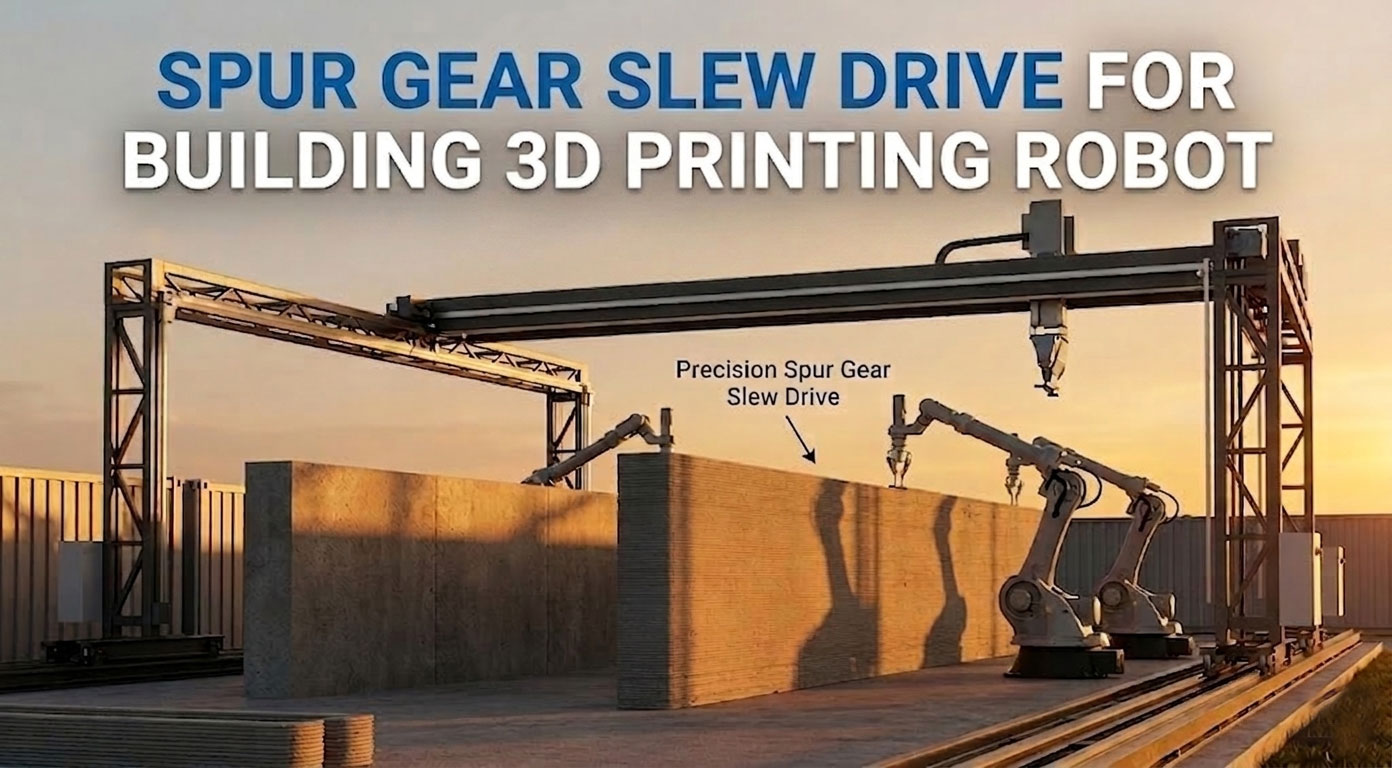
Spur Gear Slew Drive for Building 3D Printing Robot
The global construction industry is undergoing a profound paradigm shift driven by automation and large-scale 3D concrete printing (3DCP). By automating material deposition layer by layer, building 3D printing robots—whether configured as gantry systems or heavy-duty articulated arms—eliminate traditional formwork, minimize waste, and unlock unprecedented design freedom.
In this demanding arena, maintaining absolute spatial accuracy while manipulating heavy extrusion payloads across expansive working envelopes is critical. Because traditional motion control components struggle to balance high load capacity with rapid velocity, engineers are turning to optimized rotary solutions. Among these, the spur gear slew drive has emerged as the high-efficiency backbone powering the primary rotational axes of modern construction automation.
What is a Spur Gear Slew Drive in 3D Printing Robots?
A spur gear slew drive is an integrated, compact rotational mechanism engineered to deliver high torque, high speed, and robust structural support within a single unitized assembly. In the context of building 3D printing robots, this drive typically functions as the primary base rotational axis (the "waist" joint) or the heavy-duty articulation joint responsible for positioning the expansive printing arm. Structurally, it represents an advanced mechanical synergy: it integrates a precision external or internal spur gear profile directly onto the ring of a heavy-duty slewing bearing, driven by one or more matching spur pinions connected to a high-performance servo motor or hydraulic drive.
Unlike conventional gearboxes that require separate, external structural bearings to manage mechanical loads, the spur gear slew drive is designed to be a self-contained structural foundation. The internal slewing bearing acts as the primary load-carrying element, while the optimized spur gear teeth handle the dynamic transmission of rotational energy. This dual-function configuration allows the drive to serve as both a high-efficiency speed reducer and a rugged structural pivot, making it uniquely qualified to support the immense physical structures of automated construction equipment.
How Does a Spur Gear Slew Drive Work in 3D Printing?
The operational mechanics of a spur gear slew drive within a 3D concrete printing environment rely on highly efficient, direct mechanical transmission and real-time load management:
Direct-Drive Transmission and Acceleration
When the robot’s controller commands a positional adjustment along a specific toolpath, the integrated servo motor rotates the driving pinion. The teeth of this pinion mesh directly with the larger spur gear teeth cut into the slewing ring. Because spur gears transfer energy through a rolling line of contact parallel to the axis of rotation, the drive exhibits incredibly low mechanical friction. This allows for near-instantaneous power transfer, high rotational velocities, and sharp acceleration profiles, ensuring the heavy robot arm can change directions rapidly without lagging behind the digital blueprint.
Continuous Toolpath Vector Tracking
As concrete is extruded through the nozzle, the printing robot must execute complex, multi-directional geometries, including sharp corners, concentric arcs, and parabolic curves. The spur gear drive operates continuously to adjust the orientation of the primary arm assembly. The direct gear meshing enables the control system to accurately calculate and maintain a constant linear speed at the print head, which is absolutely vital for maintaining a consistent material bead width and avoiding structural defects in the curing concrete.
Dynamic Multi-Load Management
As the robotic printing arm extends outward to reach the perimeter of a structure, the physical leverage exerted on the base joint changes drastically. The internal rolling elements of the drive's integrated bearing continuously absorb these moving forces. Axial weight from the concrete-filled arm, radial forces from acceleration, and immense tilting moments generated by the cantilevered payload are distributed evenly across the bearing raceways. This ensures that the rotational motion remains fluid and uninhibited, even when the drive is subjected to maximum mechanical leverage at full arm extension.
Key Features Required for Building 3D Printing Robots
Operating on an active construction site places extraordinary demands on robotic machinery. To ensure uninterrupted operation during critical concrete pours, a spur gear slew drive must incorporate several specialized engineering characteristics:
High Angular Velocity and Continuous Operation: Concrete 3D printing is a time-sensitive process; the material must be deposited before previous layers set to ensure proper structural bonding. Spur gear drives are uniquely capable of sustaining high rotational speeds over extended duty cycles without generating excessive internal heat, a common limitation found in friction-heavy worm gear drives.
Exceptional Mechanical Transmission Efficiency: By leveraging direct rolling gear contact, spur gear configurations achieve mechanical efficiency ratings often exceeding 90%. This high efficiency minimizes internal energy loss, permitting the utilization of smaller, lighter, and more energy-efficient servo motors while still delivering the necessary torque to move massive structural frames.
High Structural Rigidity and Minimal Deflection: Even a fraction of a millimeter of physical play or sagging at the base joint can translate into centimeters of inaccurate displacement at the end of a ten-meter printing boom. The drive must feature a rigid housing and preloaded internal bearing elements to eliminate structural deflection, ensuring the print head remains perfectly level relative to the foundation.
Robust Ingress Protection and Contaminant Sealing: Construction environments are inherently hostile, characterized by airborne concrete dust, abrasive particulate matter, water spray, and changing weather conditions. The drive must be housed in a fully sealed enclosure utilizing high-grade lip seals to prevent contaminants from compromising the internal lubrication and accelerating tooth wear.
Why Spur Gears Excel in 3D Printing
Precision is the deciding factor between a successful, load-bearing automated structure and a catastrophic print failure. When managing the deposition of heavy concrete layers, the structural responsiveness of the mechanical drive determines the final quality of the building.
Elimination of Layer Artifacts and Delamination
If a rotary joint exhibits mechanical backlash or slop, the robotic arm will experience subtle micro-vibrations or positional overshooting every time it changes direction. In 3D concrete printing, these minor errors manifest as visible waviness, uneven layer lines, or internal structural voids. Precision-ground spur gears can be manufactured with extremely tight tolerances and adjustable center distances, enabling engineers to minimize rotational play. This high precision yields perfectly aligned material layers, maximizing both the aesthetic appeal and the structural compressive strength of the printed wall.
Execution of Intricate Geometric Toolpaths
Modern architecture frequently leverages 3DCP to build organic, curvilinear structures that would be cost-prohibitive to construct using traditional wood or metal formwork. Executing these smooth curves requires the rotary drives to make instantaneous, fluid adjustments to changing toolpath vectors. The low-friction, direct-mesh nature of spur gearing responds immediately to the micro-commands of the robot's CNC controller. This allows the system to transition smoothly from straight lines to intricate architectural details without stalling, dragging, or over-extruding material at the corners.
How to Select a Spur Gear Slew Drive for Building 3D Printing Robots?
Selecting the optimal drive mechanism requires a detailed analysis of both the physical robot structure and the specific material properties of the concrete being utilized:
Static and Dynamic Load Calculation
Begin by calculating the maximum structural loads the drive will encounter. This involves summing the dead weight of the robotic arms, the variable weight of the wet concrete mass traveling through the extrusion hoses, and the intense tilting moment (overturning force) created when the arm is fully extended. The selected drive must possess a static and dynamic safety factor that comfortably accommodates these combined forces without risking deformation of the bearing raceways.
Speed and Duty Cycle Parameters
Define the maximum required angular velocity (RPM) needed at the print head to match the maximum extrusion rate of the pump. Additionally, evaluate the expected duty cycle. Because concrete printing often requires continuous, uninterrupted operation for hours at a time to prevent cold joints, the drive must be rated for long-term continuous thermal stability under load.
Backlash and Positioning Tolerances
Determine the maximum allowable error at the nozzle tip. For high-end architectural finishes, choose a drive featuring precision-machined, low-backlash spur gearing. If necessary, consider dual-pinion driving configurations designed to mechanically eliminate backlash, ensuring absolute spatial repeatability down to sub-millimeter levels.
Gear Ratio and Motor Integration
Analyze the reduction ratio of the drive to ensure it matches perfectly with your chosen servo motor and secondary planetary gearbox. The ratio must be high enough to provide the necessary mechanical advantage for smooth positioning, yet optimized to allow the motor to operate within its most efficient RPM bands during high-speed travel phases.
Installation and Maintenance of Building 3D Printing Robots
Proper installation procedures and a structured preventative maintenance schedule are essential to safeguard the massive capital investment of a construction robot and ensure long-term operational reliability.
Precision Installation Protocols
Foundation Flatness: The mounting structure or chassis surface where the drive is bolted must be machined to extreme flatness tolerances. Any surface irregularity can warp the drive's housing when bolted down, distorting the internal slewing bearing raceways and causing premature failure.
High-Tensile Fasteners: Always utilize the recommended grade of high-tensile bolts (typically Class 10.9 or 12.9) to secure the drive to the robot frame. Bolts must be torqued in a progressive, star-pattern sequence using a calibrated torque wrench to ensure even clamp loading.
Backlash Alignment: Carefully align the driving pinion with the main gear ring, checking tooth clearance and backlash across multiple points of the gear's circumference to prevent localized binding.
Preventive Maintenance Routines
Lubrication Schedules: Implement a strict lubrication schedule using high-quality EP (Extreme Pressure) lithium-complex or synthetic greases. Regular lubrication flushes out old grease along with any fine dust particles that may have bypassed the external seals.
Seal Inspection: Visually inspect the integrity of the polyurethane or rubber seals before every major printing project. Damaged seals must be replaced immediately to prevent wet concrete slurry or dry dust from entering the gear teeth.
Bolt Retorquing: Due to the heavy vibration and cyclic loading inherent in robotic concrete deposition, check the torque specifications of all structural mounting bolts periodically to prevent mechanical loosening.
LyraDrive: Custom Building 3D Printing Robot Slew Drive Manufacturer for Your Application
LyraDrive is a professional one-stop slewing device manufacturer majored in design and development, customized production, sales and service on slew drives and slewing bearings. With decades of deep industry expertise and advanced manufacturing infrastructure, we deliver robust mechanical solutions engineered to withstand the most challenging industrial environments worldwide.
Recognizing the distinct operational constraints of the automated construction market, we offer highly specialized, engineering-backed solutions tailored specifically for automated building applications. Whether your project demands a lightweight aluminum alloy configuration for a mobile 3D printer or a massive, multi-pinion, high-capacity system for a multi-story gantry crane, LyraDrive can design a customized slew drive tailored precisely to your application's load, speed, and precision criteria. By optimizing tooth profiles, incorporating advanced sealing arrays, and utilizing specialized metallurgy, we ensure our assemblies mesh flawlessly with your robotic architecture to maximize operational efficiency.
Partner with LyraDrive today to elevate your automation projects with high-precision motion control solutions engineered to turn ambitious architectural concepts into structural reality.
FAQs About Spur Gear Slew Drives for Building 3D Printing Robots
Q1: Why should I choose a spur gear slew drive instead of a worm gear drive for a 3D concrete printing robot?
A: While worm gear drives offer excellent self-locking capabilities and high torque capacity, they operate via sliding friction, which limits their rotational speed and generates significant heat during continuous cycles. Spur gear configurations utilize efficient rolling contact, allowing the robot to maintain the high continuous speeds, quick accelerations, and thermal stability needed to execute long, uninterrupted architectural print paths safely.
Q2: How does a spur gear slew drive handle the heavy tilting forces when a robot arm is fully extended?
A: The unit features a highly rigid, integrated heavy-duty slewing bearing that acts as its structural foundation. This bearing utilizes specialized single-row or double-row ball or roller configurations designed specifically to absorb massive axial weight, radial loads, and severe overturning moments concurrently, preventing structural deformation at full extension.
Q3: Since spur gear drives do not have inherent self-locking capabilities, how does the robot stay in position when power is cut?
A: Because spur gears can be back-driven, systems utilizing them must integrate an external mechanical or electromagnetic brake onto the input servo motor or secondary planetary gearbox. When power is shut down or an emergency stop is triggered, this braking mechanism engages instantly to lock the entire robotic arm securely in position.
Q4: What grade of ingress protection (IP rating) is recommended for these drives on a construction site?
A: For construction automation systems exposed to airborne cement dust, moisture, and outdoor weather, it is highly recommended to select an enclosed drive featuring a minimum protection rating of IP65 or IP66. This ensures the internal gear teeth, bearing raceways, and lubricants remain completely isolated from harmful external abrasives.
Q5: Can the backlash in a spur gear drive be adjusted over time as the teeth wear down?
A: Yes, many advanced designs allow for minor adjustments. By utilizing an eccentric mounting mechanism for the driving pinion housing, operators can subtly adjust the center distance between the pinion and the main gear ring over time. This configuration compensates for natural mechanical wear, allowing you to maintain tight precision throughout the operational life of the equipment.