


Slewing Drive Efficiency: A Matter of Worm Sliding Velocity
In the world of heavy-duty rotational motion, from solar trackers to cranes, one component plays a pivotal role in performance and reliability: the slew drive. At the heart of its efficiency lies a critical yet often overlooked factor: worm sliding velocity. This article delves into why this specific parameter is a key determinant in the efficiency, selection, and longevity of a high-quality slewing drive.
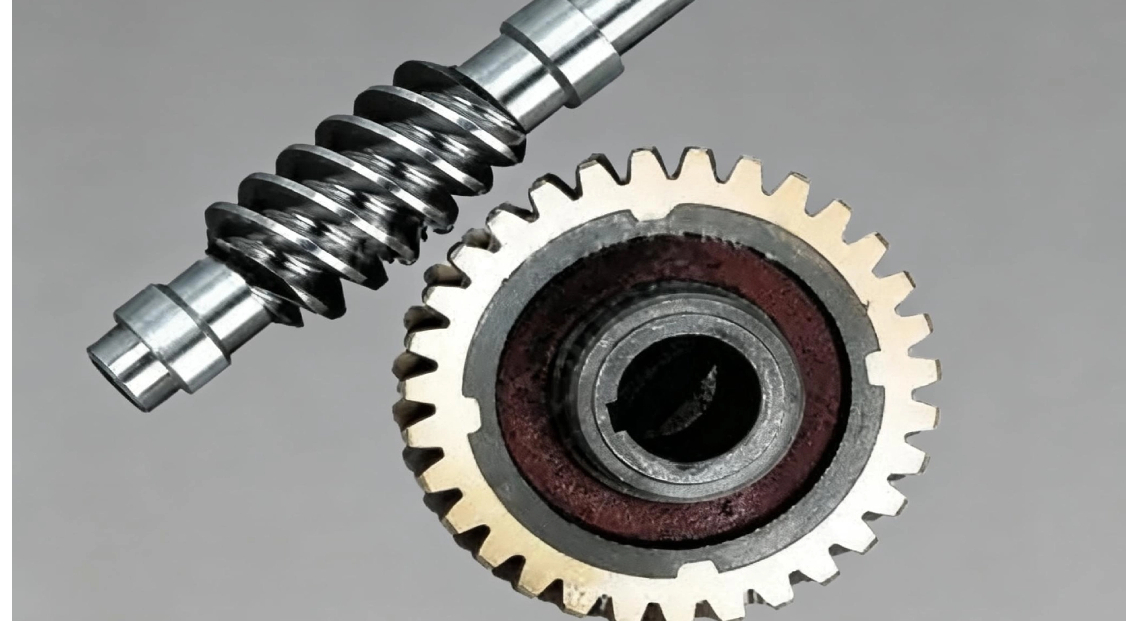
What is Worm Gear Slew Drive?
A worm gear slew drive is a compact, robust gearbox that provides 360-degree rotational movement along a single axis. It consists primarily of a worm (the input drive screw) and a worm gear (the output geared ring). Renowned for their high torque output, self-locking capability, and compact design, slew drives are essential in applications requiring slow, precise, and powerful rotation. You’ll find them in:
Solar Tracking Systems
Construction Cranes & Excavators
Wind Turbine Pitch & Yaw Control
Material Handling & Robotics
Satellite and Radar Antennas
How Does Worm Gear Slew Drive Work?
The principle is elegantly simple. The worm, typically connected to an electric or hydraulic motor, rotates. As it turns, its threads (helical grooves) engage with the teeth of the large worm gear. This engagement converts the rotary motion of the worm into a powerful, slow-rotation output of the gear. The large contact area between the worm and gear teeth allows the system to handle immense radial and axial loads while offering a high reduction ratio in a single stage. The inherent angle of the worm thread can create a self-locking effect, preventing back-driving and holding loads securely in position without the need for a brake.
Key Features of the Worm in Slew Drives
The worm is the active, driving component and its design is crucial:
Function: It is the primary torque input and motion initiator.
Material & Hardness: Typically made from case-hardened alloy steel (e.g., 20CrMnTi) and surface-hardened to high levels (HRC 58-62) to resist wear.
Precision Grinding: High-precision threads are ground after heat treatment to ensure minimal friction, smooth operation, and accurate meshing with the gear.
Lead Angle: The angle of the worm’s helix directly influences the drive’s efficiency, speed, and self-locking tendency.
How Worm Sliding Velocity Determines Transmission Efficiency
The transmission efficiency of a slewing drive is not a fixed value; it is a dynamic outcome significantly governed by a key operational parameter: worm sliding velocity. Understanding this relationship is crucial for selecting, operating, and maintaining a high-performance system.
What is Worm Sliding Velocity (Vs)?
In a worm gear set, the contact between the worm and gear teeth is not a pure rolling action. It is characterized by a significant sliding motion. The worm sliding velocity is the relative speed at which the surfaces of the worm thread and the worm gear tooth slide against each other at their point of contact. It is calculated based on the worm's rotational speed, its pitch diameter, and its lead angle.
The Direct Impact on Efficiency
Frictional power loss at this sliding interface is the primary factor reducing efficiency in worm gear drives. Here’s how sliding velocity (Vs) dictates performance:
High Friction & Heat Generation: As sliding velocity increases, so does the frictional force between the meshing surfaces. This friction converts mechanical energy into heat. Excessive heat can degrade the lubricant, cause thermal expansion of components (misaligning the gear mesh), and accelerate wear.
Increased Wear: Higher sliding speeds, especially under load, lead to more rapid wear of the tooth surfaces. This wear changes the gear geometry, further increasing backlash and reducing efficiency over time.
Lubricant Breakdown: Every lubricant has an optimal operating temperature and shear rate. High sliding velocity pushes lubricants beyond these limits, causing them to thin out, oxidize, or lose their protective film, leading to boundary lubrication and metal-to-metal contact.
Simply put: Higher Worm Sliding Velocity = Higher Friction = More Heat & Wear = Lower Transmission Efficiency and Shorter Service Life.
Key Influencing Factors and Their Solutions
The sliding velocity and its negative effects are not inevitable. They can be managed and minimized through intelligent design and proper maintenance.
| Influencing Factor | Impact on Sliding Velocity & Efficiency | Recommended Solutions |
|---|---|---|
| Worm Design & Geometry | A larger worm pitch diameter or a high input RPM directly increases Vs. An unsuitable lead angle can optimize for self-locking at the expense of efficiency. | Optimal Worm Sizing: Design the worm with a balanced combination of diameter and lead angle to achieve the required torque and ratio while minimizing Vs. Use multi-start worms for higher efficiency applications where self-locking is not critical. |
| Surface Finish & Hardness | Rough surfaces dramatically increase friction and micro-welding at high sliding speeds. Soft materials wear rapidly. | Precision Grinding & Hardening: Employ case-hardened alloy steel worms (HRC 58-62) followed by precision grinding. This creates an extremely smooth, hard surface that minimizes the coefficient of friction and resists wear. |
| Lubrication | This is the most critical operational factor. Incorrect lubricant type, viscosity, or quantity fails to separate the sliding surfaces, leading to high friction and failure. | Use High-Performance EP Lubricants: Always use Extreme Pressure (EP) grease or oil specifically formulated for worm gears. These contain additives that form a protective film under high sliding pressure. Correct Lubrication Method: Ensure proper filling of the gear cavity. For continuous operations, consider systems with automatic re-lubrication. Regularly monitor and change lubricant before thermal breakdown. |
| Operating Temperature | High ambient or operational temperature thins the lubricant, reducing its load-carrying capacity and accelerating oxidation. | Thermal Management: Select a lubricant with a high-temperature stability rating. For demanding applications, design the slewing drive housing with cooling fins or specify models with integrated heat exchangers. |
| Alignment & Load | Misalignment or shock loads create uneven contact, increasing localized sliding pressure and velocity, causing premature wear. | Precise Installation: Ensure the drive is mounted on a flat, rigid surface with proper alignment. Avoid shock loads by using controlled acceleration/deceleration. |
How to Select the Appropriate Worm for a Slewing Drive?
Choosing the right worm specification is vital for matching performance with application demands. The goal is to achieve the desired output torque and speed while minimizing sliding velocity for peak efficiency.
Understand Your Application Loads: Precisely determine the required output torque, axial/radial loads, and moment loads.
Define Speed Requirements: Know the necessary output rotational speed (often in RPM) for your function (e.g., tracking speed).
Consider the Ratio: The gear ratio will influence the worm’s required input speed. A higher ratio provides more torque but may require a different worm design to manage sliding velocity.
Prioritize Low Sliding Velocity Design: Look for drives where the worm is designed (in terms of pitch, diameter, and lead angle) to operate at an optimal, low sliding velocity for your required output speed. This often involves a balanced design rather than simply using the smallest or largest possible worm.
Material & Manufacturing Quality: Insist on case-hardened and precision-ground worms. The surface finish and hardness are non-negotiable for reducing friction and wear at the sliding interface.
Duty Cycle & Environment: For continuous or high-duty cycle operations, the sliding velocity and thermal management become even more critical.
Why Choose LyraDrive Slew Drives?
At LyraDrive, we engineer efficiency from the ground up. Our slew drives are designed with a deep understanding of worm sliding dynamics:
Optimized Worm Geometry: Our worms are meticulously calculated and manufactured to achieve an ideal balance between torque capacity and low sliding velocity, maximizing transmission efficiency and lifespan.
Premium Materials & Process: We use high-grade alloy steel, advanced case-hardening, and precision grinding to ensure a hard, smooth contact surface that minimizes friction.
Holistic Efficiency Design: We don't just design the worm; we engineer the entire system—including housing for heat dissipation and recommending the perfect high-performance EP lubricant—to manage the effects of sliding velocity.
Application-Focused Solutions: We don’t offer one-size-fits-all. We help you select or customize a drive where the worm specification is matched to your specific speed, load, and duty cycle requirements, guaranteeing optimal, reliable performance.
FAQ: Common Questions about Worm Gear Slew Drives
Q: Is the self-locking feature always present?
A: It depends on the lead angle of the worm. A low lead angle typically provides self-locking. However, for high-efficiency drives that may need to back-drive, a higher lead angle is used. Always specify your need for holding position.
Q: How do I maintain a slew drive?
A: Regular maintenance primarily involves monitoring and changing the lubricant according to the manufacturer's schedule, which is heavily influenced by operating temperature and sliding velocity. Also, periodically check for any abnormal noise or play.
Q: Can a slew drive be used for high-speed rotation?
A: Slewing drives are generally designed for slow-speed, high-torque output. High input speeds on the worm lead to excessive sliding velocity, causing overheating, rapid wear, and lubricant failure. They are not typically suitable for high-speed applications.
Q: What's the main sign of a poorly matched worm sliding velocity?
A: Persistent Overheating is the primary indicator. If the drive housing becomes excessively hot during normal operation, it often points to high friction losses due to sub-optimal sliding velocity, poor lubrication, or both.
Q: Does a larger worm always mean better performance?
A: Not necessarily. A larger worm might handle higher input power, but if not matched correctly to the gear ratio and operating speed, it can increase sliding velocity and reduce efficiency. The entire system must be balanced for your specific application.