


How to Solve Gear Backlash Problems for Slew Drives
What is Slew Drive?
A slew drive, also known as a slewing drive, is a compact, high-torque rotational actuator that is fundamental to modern automated machinery. At its core, it is an integrated system combining a worm gear mechanism, high-capacity slewing bearings, a robust housing, and often a directly mounted electric motor or hydraulic drive.
The working principle is elegantly simple yet powerful: the rotation of the worm (a threaded shaft) engages with and drives a large gear wheel. This configuration provides a very high gear reduction ratio in a single stage. This means a fast but low-torque input from the motor is converted into a powerful, slow, and precisely controlled output rotation. A key feature of the worm gear design is its inherent self-locking capability under certain conditions, which prevents the load from back-driving the motor and holds position securely without additional brakes.
Primary Application Fields:
Industrial Automation: Robotic welding arms, material handling turntables, CNC rotary tables, and automated assembly stations.
Heavy Machinery: Excavators, cranes, and radar antenna pedestals.
Renewable Energy: Solar panel tracking systems that require precise daily movement to follow the sun.
How Does a Slew Drive Work?
The core operation of a slew drive is based on a worm gear principle. A rotary input, often from an electric motor, turns the worm screw. This screw meshes with teeth on the outer edge of a large gear (the ring gear), which is directly connected to the output rotation platform. The key to its functionality lies in this specific gearing arrangement: for every full rotation of the worm, the large gear advances only one tooth. This design creates a very high gear reduction ratio, transforming high-speed, low-torque motor input into powerful, slow, and highly controllable output rotation. This controlled motion provides exceptional positional accuracy and load-holding capability, crucial for stable and precise operation.
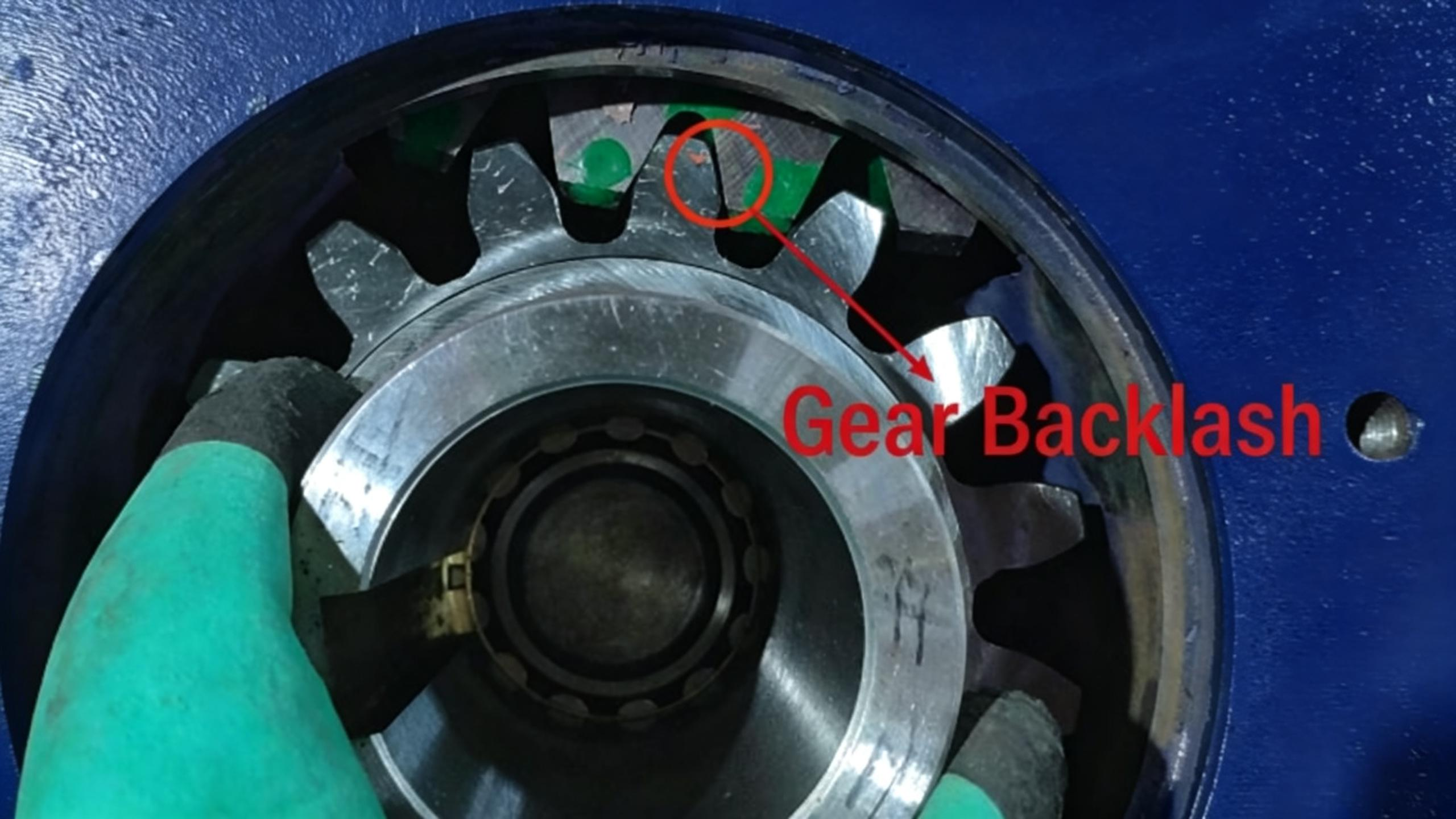
What is Gear Backlash in a Slew Drive?
Gear backlash, often called "play" or "lost motion," is the small but measurable angular movement of the output shaft of a slew drive when the input shaft is held stationary and the direction of rotation is reversed. In essence, it is the gap between the meshing teeth of the worm and the gear.
This gap is not necessarily a manufacturing defect; a minimal, controlled amount is a necessary design allowance. It ensures the gears do not jam due to thermal expansion, provides space for lubrication, and prevents excessive friction and wear. The challenge lies in minimizing this gap to a level acceptable for the application's precision requirements without compromising the drive's reliability or causing premature failure.
How Does Gear Backlash Occur?
Backlash in a slew drive arises from a combination of intentional design, manufacturing realities, and operational wear:
Design and Assembly Tolerance: No mechanical component can be manufactured with absolute perfection. Micro-level tolerances in gear tooth profile, pitch, and alignment are inevitable. When assembled, these minute variations accumulate, creating a small clearance between mating teeth. This is often referred to as "inherent backlash."
Tooth Profile and Fit: The very shape of the gear teeth (involute profile for the gear, specific thread form for the worm) is designed to allow smooth rolling motion, which naturally includes a clearance.
Operational Wear: This is the most significant factor in the growth of backlash over time. As the slew drive operates under load, constant meshing, friction, and shock loads cause gradual wear on the gear teeth surfaces. This wear removes material, effectively enlarging the gap between the teeth. Contaminants like dust or inadequate lubrication can dramatically accelerate this process.
Component Deflection: Under heavy radial or axial loads, the housing, shafts, and bearings can experience slight elastic deformation. This deflection can temporarily alter the precise meshing relationship of the gears, contributing to dynamic backlash, which varies with the load.
Impacts of Gear Backlash Problems
Excessive or uncontrolled backlash has far-reaching negative consequences for automated systems:
Loss of Positioning Accuracy and Repeatability: This is the most direct impact. When a controller commands a direction change, the motor must first rotate through the "dead zone" of the backlash before motion is transmitted to the load. This results in positional error, making it difficult to achieve precise, repeatable stops. In tasks like robotic welding or precision assembly, this can lead to defective products.
System Instability, Oscillation, and Vibration: Backlash introduces a non-linear element into the motion control loop. During rapid reversals or when stopping, the load can briefly disconnect from the drive, then re-engage with an impact. This causes jerky motion, oscillations, and increased vibration, harming the system's stability and its ability to perform smooth, controlled movements.
Accelerated Component Wear and Reduced Lifespan: The repeated impact of re-engagement after traversing the backlash gap creates shock loads. These shock loads significantly increase stress on gear teeth, bearings, and shafts, leading to premature fatigue and pitting. This creates a vicious cycle: wear increases backlash, which in turn causes more violent impacts and accelerated wear.
Reduced System Stiffness and Responsiveness: A system with high backlash feels "soft" or "springy." It cannot instantly translate motor force into load movement, degrading the dynamic response and making the system less suitable for high-speed, high-acceleration tasks.
Increased Noise: The impact of teeth colliding after traversing the backlash gap generates a distinct knocking or rattling sound, increasing operational noise levels.
How to Solve Gear Backlash Problems?
Managing backlash requires a holistic approach, combining mechanical design, manufacturing excellence, and intelligent control. Solutions can be categorized as follows:
A. Mechanical & Design Solutions (The Fundamental Approach):
These methods aim to physically reduce or eliminate the gear gap at the component level.
| Solution | How It Works | Advantage | Consideration |
|---|---|---|---|
| Precision Manufacturing | Using high-precision grinding and honing to achieve ultra-tight gear tooth tolerances and perfect profile geometry. | Provides the lowest possible inherent backlash; superior surface finish reduces wear. | Higher manufacturing cost; requires clean operating environment. |
| Preload Application | Applying a controlled axial force to the worm shaft or using a split gear design with spring tension to keep teeth in constant contact, eliminating free play. | Effectively reduces backlash to near-zero; maintains performance over a range of loads. | Increases friction and heat generation; requires precise adjustment; may reduce efficiency slightly. |
| Anti-Backlash Gear Designs | Employing specialized gear sets, such as dual-path gears with spring-loaded halves that take up clearance in both rotational directions. | Actively compensates for wear, maintaining low backlash over time. | More complex design; higher cost and weight. |
| Stiff System Design | Utilizing rigid housings, high-quality tapered roller bearings in the slewing ring, and optimized structural support to minimize deflection under load. | Reduces dynamic backlash caused by component flexing. | Can increase the size and weight of the drive unit. |
B. Control & Compensation Solutions (The Corrective Approach):
When mechanical backlash cannot be fully eliminated, electronic compensation is used.
Backlash Compensation in CNC/Controller: This software algorithm commands the motor to intentionally "overshoot" by a pre-measured backlash value (e.g., 5 arc-minutes) upon every direction reversal. This takes up the mechanical slack instantly in the control signal.
Dual-Loop Feedback: The most effective control solution. It involves using two encoders: one on the motor shaft (standard) and a second, high-precision encoder directly on the output load shaft. The controller uses the load-side encoder for the primary position feedback, making the mechanical backlash inside the drive "invisible" to the control loop. This is crucial for ultimate accuracy.
C. Operational & Maintenance Best Practices:
Proper Lubrication: Using the correct grade and quantity of high-quality grease forms a protective film, minimizing wear and slowing the growth of backlash over time.
Regular Inspection & Re-adjustment: For drives with adjustable preload, periodic maintenance to check and reset preload can restore original performance.
Load Management: Avoiding sudden shock loads and operating within the drive's rated capacity extends component life and limits backlash increase.
LyraDrive: Committed to Designing and Manufacturing High-Performance Slew Drives
LyraDrive is a leading one-stop manufacturer, specializing in the design, development, and production of high-performance slew drives and slewing bearings—the compact, integrated systems that deliver controlled, powerful 360-degree rotation for equipment worldwide. We understand that managing gear backlash is not an afterthought but a core design requirement for reliable automation.
Our slew drives are built with precision-ground worm gearsets manufactured to the tightest tolerances, ensuring minimal inherent backlash. We offer integrated preload adjustment systems in our standard designs, allowing for optimal tuning during assembly and future maintenance. For the most demanding applications, our dual-encoder ready designs facilitate the implementation of absolute closed-loop control, guaranteeing the highest level of positioning accuracy regardless of mechanical wear.
From compact internal gear drives for space-constrained robotic cells to robust heavy-duty drives for large-scale automation turntables, every LyraDrive product is a balance of strength, precision, and longevity. We partner with our clients to deliver not just a component, but a certified motion solution that solves the backlash challenge and enhances the performance of your automated equipment.
FAQ of Gear Backlash in Slew Drives for Automated Equipment Applications
Q1: Is zero backlash possible or desirable in a slew drive?
A: True zero backlash is extremely difficult and often undesirable in practice. It can lead to excessive friction, heat buildup, rapid wear, and potential binding. The engineering goal is to minimize backlash to a level that is functionally negligible for the specific application, often in the range of 1 to 5 arc-minutes for precision automation.
Q2: Can backlash be measured on installed equipment?
A: Yes, a simple manual test can give an indication. Mark the output flange. Use the motor to slowly rotate in one direction until movement is just detected at the load. Reverse the motor command slightly until the load just starts moving back. The motor's angular movement between these two points (often readable from the controller) is a proxy for the total system lost motion, which includes backlash.
Q3: Does backlash get worse over time?
A: Yes, this is a normal characteristic. As gears wear, the clearance between teeth increases. A high-quality slew drive is designed for minimal initial backlash and slow, predictable wear progression. A sudden increase in backlash or noise often indicates abnormal wear or damage.
Q4: What's more important for reducing positional error: high motor encoder resolution or low mechanical backlash?
A: Both are important, but they address different issues. A high-resolution motor encoder allows for very fine control of the motor shaft position. However, low mechanical backlash ensures that this precise motor movement is accurately transmitted to the load without delay or loss. For ultimate accuracy, you need both, often complemented by a load-side encoder (dual-loop feedback).
Q5: Can I retrofit an old slew drive to reduce its excessive backlash?
A: Options are limited. Adjusting preload (if the design allows it) can recover some performance. However, if the gears are significantly worn, the only permanent solution is replacement of the worn gearset or the entire drive unit. Regular maintenance and proper lubrication are the best ways to extend service life and delay this scenario.