



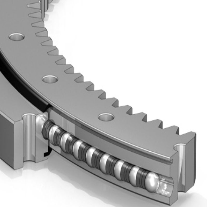
What is a slew drive? A slew drive is a compact, enclosed unit that combines a slewing bearing, a gear set (usually a worm gear) and a housing. A motor turns the worm, and the worm turns the output ring to rotate or position a load.
After a slew drive motor replacement, the drive is mechanically unchanged, but the electrical start-up conditions are not. Polarity, rotation direction, current limits and limit-switch wiring can all differ from the failed motor. This article gives field technicians a diagnosis order for the first run, with clear observations and next actions.
What Goes Wrong at the First Start After a Motor Swap
Most first-run faults fall into three groups: the output turns the wrong way, the controller trips on overload, or the unit travels past its intended stop. Each one is a symptom. None of them proves a single cause yet.
A reversed output could be a wiring mistake. It could also be a motor whose terminal markings differ from the old one. An overload trip could be a wrong current setting, a seized coupling, or a real mechanical problem inside the drive.
Keep observations and suspected causes separate in your notes. Write what you saw ("tripped at start, output did not move") before writing what you think caused it. That habit saves hours when you later need to hand the case to support.
Stop conditions
- Grinding or knocking from the gear housing: stop and do not retry.
- Output keeps moving after a limit switch should have stopped it: cut power immediately.
- Smoke, a hot-insulation smell, or a motor case too hot to touch: stop and inspect the wiring and the motor.
Preliminary Checks Before You Apply Power
Do the accessible checks first. They take minutes and rule out the most common causes before any live test.
- Isolate and support the load. Lock out the power source. Worm drives are often self-locking, but do not rely on that alone. Support any suspended or unbalanced load mechanically.
- Record the old setup. Photograph the terminal block, wire colors, tags and any brake or sensor connections before disconnecting. If the original wiring diagram exists, find it now.
- Compare nameplates. Put the old and new motor data side by side: rated current, voltage, speed, mounting flange and shaft type. A mismatch here explains many later trips.
- Check the mechanical fit. The motor flange should seat fully on the drive. The shaft should turn the worm with no binding when rotated by hand, where the design allows.
- Inspect seals and cable entries. Slew drives can be protected up to IP66, and that protection only holds if the motor interface and cable glands are reassembled correctly.
Sealing matters in the field. For example, we supplied 50 units of the SP-I Slew Drive (SP-I 0841) to a US renewable energy equipment manufacturer for utility-scale solar trackers at IP65-rated desert sites. A motor change in a dusty location should end with the same sealing care as the factory build.
How Polarity, Rotation Direction, Current Limits and Limit Switches Prevent Startup Faults
These four items cause most startup faults after a motor changeout. The new motor can be the right size and still fail at first run if one of them is wrong. The table gives a diagnosis order, from the item that is quickest to check to the one that needs a live test.
| Check (in order) | Fault it prevents | What to observe | What it may indicate / next action |
|---|---|---|---|
| 1. Limit-switch wiring (power off) | Overtravel, switch damage | Press each switch by hand and watch the controller input. Confirm the right switch stops the right direction. | If both switches stop the same direction, or none register, the wiring or the normally open/normally closed type is wrong. Correct it before any motion. |
| 2. Current limit settings (power off) | Nuisance trips, or no protection | Compare overload relay or drive current limit to the new motor's nameplate current. | A setting copied from the old motor may not fit. Set to the new nameplate. If no nameplate value exists, request it from the motor maker. |
| 3. Polarity or phase order | Reverse rotation | Match terminal markings to the old motor. For DC, check plus and minus. For three-phase AC, check phase order. For hydraulic, check port A and B. | Terminal markings can differ between motor brands. Do not assume the colors match. |
| 4. Rotation direction (short jog, no load if possible) | Driving into a stop or the wrong way | Jog briefly toward the middle of travel and compare the output direction to the command. | If reversed, stop and swap polarity or two phases, whichever applies. Then repeat check 1, because some limits are direction-linked. |
| 5. Brake or feedback device (if fitted) | Motor hums but does not turn, or position errors | Confirm the brake releases when commanded. Confirm encoder direction matches the controller. | A brake that stays engaged looks like an overload. A reversed encoder can cause runaway or a following-error fault. |
Why this order? Limit switches protect the machine, so they come first. Current limits protect the motor and wiring. Rotation direction comes last because it needs power, and by then the protections are already confirmed.
One limit: output direction depends on more than the motor. The worm hand (right or left) and the gear arrangement also set it. Do not use a different drive's direction as a reference. Use the original machine's drawing or the old motor's recorded wiring.
Request Your Custom Slew Drive or Bearing Spec
Tell us your load, speed, and environment — receive a tailored 100–5000 mm slewing drive or slewing bearing proposal with 3D drawings within 24 hours.
Diagnostic Branches for the First Run
Run the first test at the lowest practical speed, with a clear travel path and a person on the emergency stop. Then match what you see to the table below. The causes are possibilities, not conclusions.
| Observation | Possible causes | Next check |
|---|---|---|
| Output turns the wrong way | Polarity, phase order or hydraulic port swap; reversed encoder | Compare terminals with the photo of the old setup. Swap one pair only, then retest. |
| Trips immediately at start, no output motion | Current limit set too low; short in wiring; brake not releasing; locked coupling | Check settings against the nameplate. Measure insulation. Confirm brake release. Turn the shaft by hand if possible. |
| Trips after several seconds of travel | Load higher than expected; binding in the drive; limit set too tight; overheating | Compare running current with the nameplate. Check for rough spots through the whole rotation. |
| Motor hums but does not turn | Missing phase; low supply voltage; brake engaged; hydraulic flow blocked | Check all supply conductors and voltage at the motor terminals. Check the brake. Check valve settings. |
| Output does not stop at the limit | Switch wired to the wrong input; wrong switch type; switch not aligned with the cam or target | Stop. Repeat the hand test from the table above. Check switch alignment before any further powered motion. |
| New noise or rough motion after restart | Coupling misalignment; worm shaft damage; lubrication problem; contamination | Stop. Inspect the motor interface and the grease for metal particles. Escalate if present. |
After any corrective action, repeat the same short test. The symptom should change in a way that matches your suspected cause. If it does not, the cause is not settled, so keep the alternative explanations open.
A Step-by-Step First-Run Verification
- Confirm limit-switch function by hand with power off.
- Confirm current limit settings against the new motor nameplate.
- Power up and check for fault codes before commanding motion.
- Jog a few seconds in one direction. Confirm direction and the correct limit input.
- Jog the opposite direction. Confirm the opposite limit input.
- Run a slow sweep through the full travel with no load or a light load.
- Record the running current and listen for changes in sound along the travel.
- Run at normal speed, then add the working load in steps.
- Re-check fasteners, cable glands and seals after the first hour of operation.
This sequence suits most worm-driven units, including a worm gear slew drive on a crane or platform. Where the machine has special safety logic or interlocks, follow the machine builder's procedure first. This list does not replace it.
Common Mistakes During Slew Drive Motor Replacement
- Copying the old current setting. The failed motor may have had a different rating. Always use the new nameplate.
- Trusting wire colors. Colors vary between suppliers. Use terminal markings and your photos.
- Testing limits with power on. A wrong wire can drive the unit into its stop. Test by hand first.
- Swapping several things at once. You lose track of what fixed or changed the problem. Change one item, then retest.
- Retrying after a grinding noise. This can turn a wiring issue into gear damage.
- Skipping the seal check. Moisture or dust entering at the motor interface can cause faults weeks later.
Some drive types need extra attention. A double worm slew drive has two worm paths, so a change in motor setup should be checked against the original design. In our supply, the Houston, Texas customer used 150 units of WED17-104-25HR for heavy-duty wheel steering, where direction errors matter. The same care applies to any drive on steering or positioning duty.

Prevention, Records and When to Escalate
Keep a one-page record for each drive: motor nameplate data, wiring photos, current setting, limit-switch positions and first-run current. The next technician can then compare numbers instead of guessing. It also makes a warranty or support review much faster.
Escalate when you see metal in the grease, unexplained backlash, repeated trips after correct settings, or any overtravel you cannot trace to wiring. Send this to support:
- Drive model and serial number, plus the motor nameplate
- Wiring diagram or marked photos of the terminals
- Current settings and measured running current
- Fault codes, with a short video of the first run if possible
- Load type, duty cycle and environment
Luoyang Slewring Bearing Co., Ltd. offers a 48-hour technical response, and our products carry a 2-year extended quality warranty. Confirmed manufacturing defects are replaced free of charge. A first-run fault is not automatically a defect, and many trace back to wiring or settings. That is why the evidence above matters.
Our production runs under an ISO 9001:2015 quality system, and each slew bearing passes CMM three-coordinate inspection. You can read more on our slew drive quality control page. If your application needs a different motor interface or mounting, a customized slew drive can be specified so that the motor swap is simpler in the field. Customized orders start at 5 sets, and standard products at 1 set.
Our own experience supports one simple rule. Prove the protections first, then the direction, then the load. Done in that order, a motor changeout becomes a short, predictable job.
Request Your Custom Slew Drive or Bearing Spec
Tell us your load, speed, and environment — receive a tailored 100–5000 mm slewing drive or slewing bearing proposal with 3D drawings within 24 hours.
 WhatsApp

 +8613903880726