



What is a slew drive? A slew drive is a compact rotary transmission unit that combines a slewing bearing, gear system, housing, and input drive to rotate equipment under load. It is used in solar trackers, cranes, excavators, turntables, forestry machines, aerial platforms, and other equipment that requires controlled angular movement.
Before starting a slew drive backlash adjustment, service teams need to answer one question: is the observed movement caused by adjustable gear-mesh clearance, or is it caused by wear, loose mounting hardware, structural distortion, or tooth damage? The correct answer determines whether an adjustment is appropriate or whether the unit needs repair, replacement, or a mounting-system inspection.
Backlash is not automatically a fault. A small amount of lost motion can be designed into a gear system to prevent binding, allow lubrication, and accommodate temperature changes. The problem begins when the movement becomes inconsistent, increases over time, produces noise, affects positioning, or occurs with visible structural movement.
For service managers, purchasing teams, and maintenance engineers, the safest rule is simple: diagnose the source before changing preload or mesh position. Tightening an adjustment to hide a structural problem can increase friction, overload internal parts, and create binding during rotation.
Start With the Reported Symptom Instead of the Suspected Cause
A report such as “the drive has too much backlash” is a symptom report, not a confirmed diagnosis. The operator may be seeing delayed movement, oscillation after stopping, poor tracking accuracy, uneven rotation, or a platform that shifts under load. Each symptom can originate from more than one location.
First, record how the issue appears. Observe the drive in both directions, under the normal working load if safe, and with the load removed if the equipment design allows it. Compare the motion at the motor input, the drive housing, the mounting interface, and the output structure.
Questions to answer before any setting is changed
- Did the symptom appear suddenly or gradually? A sudden change can point to a loose fastener, impact event, broken tooth, or mounting shift. A gradual increase may indicate normal wear, bearing wear, or progressive gear contact wear.
- Is the movement the same through the full rotation? A change at one angular position may indicate localized tooth damage, mounting distortion, or a deformed mounting surface. Uniform movement is more consistent with general clearance, although it is not proof.
- Does the housing move relative to its mounting structure? Visible movement at the mounting interface points first to fasteners, bolt holes, mating surfaces, or structural stiffness. Do not adjust gear mesh until this is corrected.
- Is there noise, roughness, or a high-effort zone? Grinding, clicking, tight spots, or intermittent resistance require investigation before adjustment. Reducing clearance in a damaged or distorted system can make those conditions worse.
- Has the application changed? A new attachment, higher duty cycle, altered center of gravity, or different operating environment can change loading conditions and expose a previously hidden installation issue.
Review maintenance records at this stage. Look for recent transport damage, welding near the mounting structure, replacement of a motor or gearbox, changes to the driven structure, or prior attempts to tighten the drive. These facts often shorten the diagnosis.
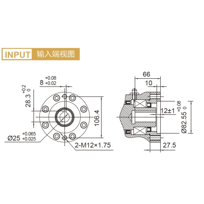
If the equipment uses a Worm Gear Slew Drive, also identify whether its design has an approved adjustment provision. Not every drive should be adjusted in the field. The product drawing, service documentation, and original supplier guidance define whether a mesh setting is accessible and how it must be checked.
Use an Ordered Inspection Path Before Touching the Mesh Setting
The best inspection order moves from accessible external checks to internal causes. This avoids opening or adjusting a serviceable drive when the real fault is in the structure around it. It also protects the service team from turning a correct gear setting into an over-tight condition.
- Secure the equipment and remove unintended motion. Isolate the power source, support the load where required, and follow the equipment manufacturer’s safety procedure. Do not perform a test that can move a suspended, elevated, or unstable structure.
- Mark reference points. Place visible marks across the drive housing and mounting structure, and across any accessible driven flange. These marks help identify whether movement comes from the housing, mounting joint, or output connection.
- Check mounting fasteners and mating surfaces. Look for missing hardware, loose hardware, elongated holes, paint crushing, fretting marks, cracked welds, or gaps between contact surfaces. Any of these signs means the mounting system must be addressed before gear adjustment.
- Check directional lost motion. With the input stopped, reverse the applied force carefully and observe where motion begins. Watch the motor shaft or gearbox input, then the housing, then the output structure. The first component that moves helps locate the clearance.
- Rotate through the working range. Note whether resistance, sound, or lost motion changes by position. A repeating tight area or clicking point is a warning sign for damaged teeth, distorted mounting, contamination, or internal damage.
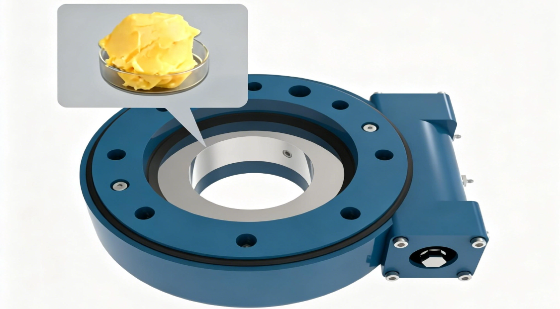
- Inspect lubrication condition and sealing condition. Leakage, contamination, dried lubricant, or damaged seals do not prove the cause of backlash, but they can support a wear-related diagnosis. Do not assume lubricant alone will correct mechanical clearance.
- Compare findings with the product documentation. Use the approved assembly drawing, installation instructions, and service limits supplied for the exact drive model. Do not apply settings from another size, series, or supplier.
Stop the field inspection and escalate when rotation is rough, teeth appear damaged, the drive binds at any point, the housing shifts under load, or the inspection cannot separate mounting movement from internal movement. Continued operation under these conditions can increase damage.
Luoyang Slewring Bearing Co., Ltd. can support technical review with a proposal within 24 hours when the model, application, photos, and observed symptoms are provided. Our engineering team works with standard and Customized Slew Drive designs, so the review can consider load direction, speed, environment, and mounting arrangement rather than treating every backlash report as the same problem.
Separate Adjustable Gear-Mesh Clearance From Structural and Wear-Related Backlash
This is the key diagnostic boundary. Adjustable gear-mesh clearance is only one possible source of lost motion. Backlash caused by bearing wear, loose fasteners, mounting distortion, or damaged teeth is not corrected by simply reducing mesh clearance.
| Observed condition | What it may indicate | Next action | Why mesh adjustment may not apply |
|---|---|---|---|
| Lost motion is consistent, rotation is smooth, and the housing remains fixed | Possible gear-mesh clearance within an adjustable drive design | Confirm that the exact model has an approved adjustment method, then follow supplier documentation | Adjustment is only suitable after mounting, bearing condition, and tooth condition have been checked |
| Housing or flange moves relative to the mounting structure | Loose fasteners, poor contact between mating surfaces, elongated holes, or structural movement | Correct the mounting fault and recheck movement | Changing mesh will not stop external joint movement |
| Movement increases under load and is accompanied by rocking at the output | Possible bearing wear, raceway damage, or deformation in the driven structure | Stop adjustment work and obtain technical evaluation | Reducing gear clearance can increase load on an already worn internal assembly |
| Clicking, grinding, or a repeated rough point occurs at one position | Possible damaged teeth, contamination, localized wear, or mounting distortion | Inspect the gear system and mounting geometry; escalate if internal inspection is needed | Tightening mesh against damaged teeth can cause binding and faster failure |
| Rotation becomes stiff after a previous adjustment | Excessive preload, incorrect mesh setting, or distortion under installation load | Stop operation where safe to do so and verify the setting against approved documentation | A tighter setting is not automatically a better setting |
Conclusion: adjust only when the evidence points to gear-mesh clearance and the specific slew drive is designed for adjustment. This fits a smooth-running unit with stable mounting, no localized damage signs, and documented adjustment instructions. It does not fit a unit with structural movement, rough rotation, damaged teeth, or suspected bearing damage.
For example, a solar tracker may show delayed reversal during positioning. If the housing remains fixed, rotation is smooth through the travel range, and no tight point appears, the service team can check whether the installed drive has an approved mesh-setting procedure. If the same tracker rocks at the foundation interface, the correct first repair is the mounting connection, not the internal gear setting.
In utility-scale solar applications, drive selection and installation quality both affect tracking results. Luoyang Slewring Bearing Co., Ltd. supplied 50 units of SP-I 0841 drives to a U.S. renewable energy equipment manufacturer for desert-site solar tracker systems with IP65 protection. That application example supports the need for environmental and mounting checks, but it does not mean every solar tracker symptom has the same cause.
Request Your Custom Slew Drive or Bearing Spec
Tell us your load, speed, and environment — receive a tailored 100–5000 mm slewing drive or slewing bearing proposal with 3D drawings within 24 hours.
Know When an Adjustment Can Create Binding Instead of Solving the Problem
Reducing clearance changes the contact relationship between the gear elements. If the original motion comes from worn bearing elements, distorted mounting surfaces, or damaged teeth, a tighter setting can transfer the problem into higher friction and uneven rotation.
Binding often appears as a tight zone rather than constant resistance. The drive may turn freely in one position and become hard to turn at another. This pattern should not be treated as a reason to tighten further.
Common mistakes that increase repair risk
- Adjusting before checking fasteners. This can hide the real source temporarily while the mounting joint continues to move. Recheck the interface first.
- Using only unloaded movement as the diagnosis. Some faults become visible only when the normal application load is applied. Compare safe unloaded and loaded observations when possible.
- Assuming all backlash comes from the worm gear. The input gearbox, motor coupling, output structure, bearing assembly, and mounting joint can all contribute to apparent lost motion.
- Correcting a tight spot with more force. Increased motor torque may push through damage but does not correct it. It can also mask the evidence needed for diagnosis.
- Applying another model’s service method. Drive geometry, materials, seals, bearing arrangement, and adjustment provisions differ by series. Use only the documentation for the installed model.
- Declaring a manufacturing defect without evidence. Wear, installation distortion, overload, contamination, and loose mounting must be considered. Evidence protects both the equipment owner and the supplier.
A field adjustment should be followed by a result check. Rotate the drive through the working range, observe for smooth motion in both directions, verify that no new tight point has appeared, and repeat the original symptom test. If the symptom is unchanged or resistance increases, stop and return to diagnosis rather than making repeated setting changes.
Our ISO 9001:2015-certified facility uses CMM three-coordinate inspection and dynamic load testing for every slewing bearing according to our quality-control process. These production controls support consistent product verification, but field performance still depends on correct mounting, application loading, maintenance, and installation alignment.
Match the Corrective Action to the Confirmed Evidence
After inspection, classify the result as an adjustable condition, a mounting repair, an internal repair evaluation, or a replacement decision. This keeps purchasing and maintenance teams from ordering parts before they know what part is actually responsible.
| Confirmed or likely finding | Appropriate action | Result to verify | When replacement may be considered |
|---|---|---|---|
| Approved adjustable mesh clearance with no other fault signs | Use the manufacturer-approved setting process for the exact model | Smooth full-range rotation and improved directional response without binding | If correct setting cannot be maintained or internal wear is found |
| Loose mounting hardware or distorted mounting contact | Repair the mounting interface, correct contact surfaces, and verify structural stability | No relative movement between housing and structure during reversal | If the mounting structure cannot be restored to a suitable condition |
| Suspected bearing wear or raceway damage | Escalate for technical assessment and determine whether repair is practical | Inspection evidence confirms the internal condition | When internal damage, service conditions, or repair economics do not support reuse |
| Damaged or worn gear teeth | Stop adjustment attempts and inspect the affected gear components | No damaged contact surfaces remain in the working path | When tooth damage affects reliable operation or replacement components are not practical |
For heavy-duty cyclic work, a repair decision should consider the application rather than only the visible symptom. A mining excavator, crane, or forestry grapple can impose changing loads that expose distortion or wear more quickly than a lightly loaded indexing table. Where load direction is demanding, a Double Worm Slew Drive may be evaluated for a new equipment design, but it is not a retrofit cure for an existing mounting fault.
A real application example is the Canadian forestry equipment project using WED14-86-25BHR.5 double worm slew drives for grapple machines, with tracking precision of no more than 0.13 degrees. That case shows that application requirements can be specific. It should not be used as a general field tolerance for unrelated drives, equipment, or service decisions.
Prepare Useful Evidence Before Escalating to the Drive Supplier
When service personnel reach a stop condition, good evidence speeds up the technical review. A clear report can prevent unnecessary disassembly and help determine whether the next step is an installation correction, repair review, or replacement quotation.
Send this information for a technical assessment
- Drive model number, serial information if available, and product photos from several angles.
- A short video showing reversal motion, housing movement, and any noise or tight point.
- Photos of mounting bolts, mating surfaces, flange contact areas, and visible tooth condition where accessible.
- A description of the equipment, load direction, duty cycle, operating environment, and any recent application changes.
- The location of the symptom within the rotation range and whether it changes under load.
- Maintenance history, lubrication observations, previous repairs, and any prior mesh-setting attempts.
Luoyang Slewring Bearing Co., Ltd. offers a 48-hour technical response and a two-year extended quality warranty with free replacement for confirmed manufacturing defects. The warranty boundary matters: a confirmed manufacturing defect is different from damage caused by mounting distortion, loose hardware, operating conditions, or component wear.
For new sourcing projects, standard products can be ordered from one set, while customized products have a five-set minimum order quantity. Sample orders are welcome for testing and evaluation. Our standard production cycle is nine days, and rapid prototyping can be completed in three days when the project requires a new design direction.
A careful slew drive backlash adjustment process begins with evidence, not a wrench. Check the mounting system, confirm where movement begins, look for uneven rotation or damage, and use an approved mesh-setting method only when the diagnosis supports it. That approach reduces avoidable binding, protects the drive, and gives procurement teams a clearer basis for repair or replacement decisions.
Request Your Custom Slew Drive or Bearing Spec
Tell us your load, speed, and environment — receive a tailored 100–5000 mm slewing drive or slewing bearing proposal with 3D drawings within 24 hours.
 WhatsApp

 +8613903880726