



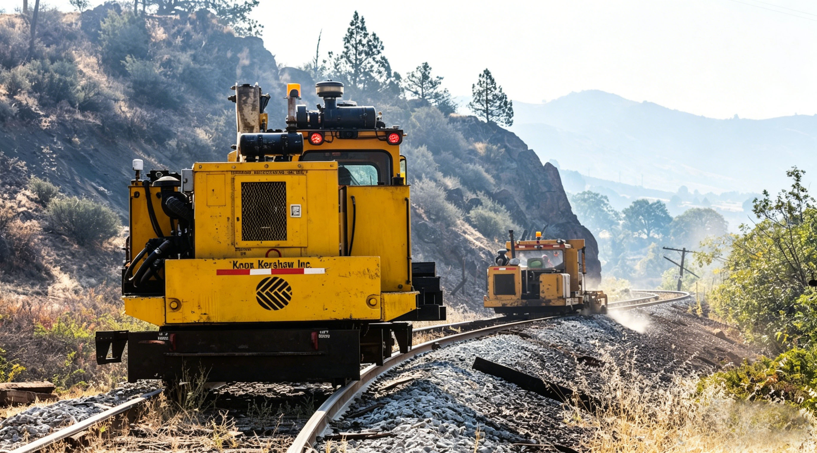
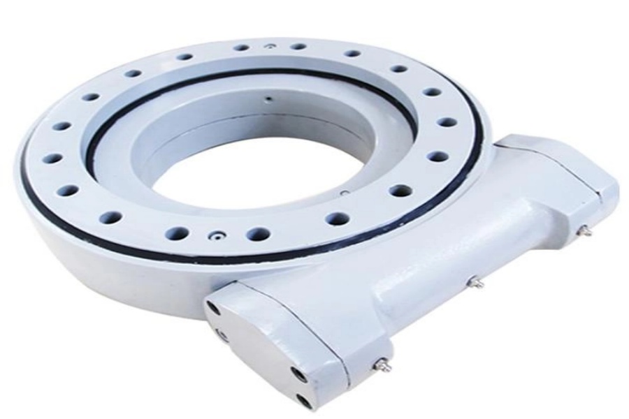
What is a slew drive? It is a compact rotation unit that combines a slewing bearing, a gear set, a housing and a motor interface in one assembly. On a lift, it turns the boom or turret.
Controls engineers face a real tension when they pick a slew drive for aerial platform work. A higher ratio feels calm but limits top speed. A tighter mesh tracks better but demands cleaner tuning. The mechanical choice on the drawing sets the ceiling for what the controller can ever do.
This article is for teams that already shortlisted a drive type and now need to validate boom-rotation behavior before production release. We link each mechanical parameter to what the operator feels at the joystick. We also say plainly where our evidence ends.
What the Controller Needs From the Drive
Operators judge a lift by four moments: the start, the creep, the stop and the hold. A controller can shape the command it sends. It cannot remove free play, stored elasticity or brake lag that the hardware adds.
Most lifts add one more layer. Two stations, one on the ground and one in the basket, can command the same rotation axis. That means the drive must behave the same way no matter who is in control.
A note on evidence. Our case library has no aerial-platform project, so this article uses general application analysis and one clearly labeled illustrative scenario. The documented cases we cite later come from other machines. They show what our drives have done, not what they will do on your boom.
How Drive Ratio, Backlash, Brake Response, Encoder Feedback and Control Handoff Affect Smoothness and Overshoot
These five items interact. Read the table as a checklist for your design review, not as a ranking.
| Factor | Effect on smoothness and overshoot | Fits when | Limit |
|---|---|---|---|
| Drive ratio | A higher ratio multiplies motor torque and cuts the load inertia the motor "feels" by the ratio squared. Low-speed motion gets smoother and overshoot drops. | Fine positioning with a loaded basket at full reach | It caps output speed at motor top speed divided by the ratio. Check cycle-time targets before you raise it. |
| Backlash | Free play creates a dead zone at direction reversal. The controller sees no motion, raises command, then the load jumps. This causes hunting and a felt "clunk." | Positioning near structures, frequent reversals | Lower backlash does not fix boom flex. Tighter mesh also adds friction. Confirm the actual figure on the drawing. |
| Brake response | If the brake sets before speed reaches zero, the stop jerks. If it sets late, the boom overshoots. The brake timing must match the deceleration ramp. | Any lift that must hold position when power drops | Self-locking depends on gear lead angle and ratio. Do not assume it. A self-locking drive still does not make a stop gentle. |
| Encoder feedback | A motor-side encoder gives a clean speed loop but cannot see backlash or boom twist. An output-side encoder sees true position but adds delay that can destabilize the loop. | Motor encoder for speed, output encoder for position limits and handoff checks | Dual-loop tuning takes bench time. The sensor also needs sealing that matches the drive's ingress rating. |
| Ground/platform handoff | If the two stations send different commands at the switch, the axis sees a step. Result: a jerk or a brief overshoot. | Dual-control lifts | Handoff logic lives in the controller, not the drive. Hardware cannot cure a bad switchover. |
Practical reading of the table
- Set the ratio first. Everything else is tuned around it. A ratio change late in the project forces a new tuning pass.
- Treat backlash as a budget. Total free play includes the gear mesh, the bearing clearance and the mounting stiffness. The mesh is only one part.
- Tie brake timing to the ramp. Write both numbers on the same test sheet.
- Define one handoff rule. For example, command zero at the switch, then ramp up. Test it with both stations.
Matching the Drive Type to the Control Strategy
Once you know the control strategy, the gear type follows. Our Aerial Work Vehicle Slew Drive and Manlift Slew Drive pages cover the category. The table below covers the control side.
| Drive type | Documented use in our cases | Control implication | Check before you commit |
|---|---|---|---|
| Worm Gear Slew Drive (single worm) | WEA9-62-25HR for port cranes: ≤0.15° tracking precision, IP65, self-locking | Can hold position without power, so brake logic is simpler | Worm gearing typically runs at lower efficiency than spur gearing. Check heat at your duty cycle. |
| Double Worm Slew Drive | WED14-86-25BHR.5 for forestry grapple machines: ≤0.13° precision | Suited to tighter positioning targets | Confirm envelope, mounting and torque against your turret. |
| Spur Gear Slew Drive | SP-I 0841-32.1 for automated turntables; SP-I units for solar trackers | Typically not self-locking, so the brake carries the holding duty and must be sized for it | Not a fit where the boom could back-drive the motor and you have no sized brake. |
For most manlift booms, we would start the discussion with a self-locking worm design. The reason is simple: a power loss should not let the boom drift. If your control team needs the tightest positioning, ask about the double worm option. Our WED Slew Drive page lists that series.
Request Your Custom Slew Drive or Bearing Spec
Tell us your load, speed, and environment — receive a tailored 100–5000 mm slewing drive or slewing bearing proposal with 3D drawings within 24 hours.
What Our Cases Show and What They Do Not
These are documented projects. None of them is an aerial platform.
- South Korean port equipment maker: 20 units of WEA9-62-25HR single worm slew drives for port crane systems. Recorded specs: ≤0.15° tracking precision, IP65 sealing, self-locking.
- British Columbia forestry equipment maker: 30 units of WED14-86-25BHR.5 double worm drives for forestry grapple machines, with ≤0.13° precision.
- Manchester automation equipment maker: 100 units of SP-I 0841-32.1 for automated turntable systems.
- Houston engineering machinery maker: 150 units of WED17-104-25HR double worm drives for heavy-duty wheel steering systems.
What the evidence supports: these drive models have been built and delivered at volume with the listed precision and sealing. What it does not support: any claim about how they would feel on a boom with a basket, a wind load and two control stations.
The precision figures belong to those machines and their control setups. They are not a promise for yours. A different boom length, payload or encoder placement changes the result, so validate on your own prototype.
Illustrative Scenario: Validating Boom Rotation Before Release
This is an illustrative sequence, not a completed customer project. It shows how a controls team might test a shortlisted drive on a bench rig or first prototype.
- Fix the speed profile. Write down the maximum slew speed, ramp-up time and ramp-down time the operator should feel.
- Test unloaded first. Run slow reversals to expose backlash. Log command and position on the same time base.
- Add rated load at full reach. Repeat the stop test from low and high speed. Record how far the boom travels past the target.
- Time the brake. Compare the brake set point against the point where speed hits zero. Adjust until they line up.
- Test the handoff. Switch from ground to platform while the axis is still, then while it is moving. Look for a step in the command.
- Cycle for heat and repeatability. Run a long duty block. Check that stop position and brake behavior do not drift.
In my design reviews over the years, the stop test under load at full reach finds more problems than any other single step. Do it early.
Common Integration Mistakes
- Choosing the ratio from motor torque alone. Check speed and reflected inertia as well.
- Quoting gear backlash as total free play. Bearing clearance and mounting flex add to it.
- Assuming "self-locking" without a check. Confirm it for the exact ratio and vibration conditions.
- Putting the only encoder on the motor. You then cannot see the real boom position.
- Testing handoff only at standstill. Moving handoff reveals the step in command.
- Tuning on an unloaded bench and releasing. Load changes the response, so retest with payload.
Boundaries and the Inputs We Need to Assess Your Boom
The approach in this article fits when you have a shortlisted drive type, a defined speed profile and a prototype or bench rig for testing. It does not replace that testing. It also does not apply if the brake, encoder or handoff logic is still undefined, because then the drive cannot be judged alone.
Open items we cannot settle from here include your exact backlash budget, your required stop distance and your duty cycle. Treat each as a verification task.
To assess another application, send us this checklist:
- Rated payload and maximum reach
- Maximum slew speed and ramp times
- Overturning moment and axial/radial loads on the turret
- Stop-position tolerance at the basket
- Brake type and where the encoder will sit
- Number of control stations and the handoff rule
- Environment, including washdown, dust or coastal exposure
Luoyang Slewring Bearing Co., Ltd. is ISO 9001:2015 certified. Our slew drives are available with protection up to IP66 and anti-corrosion ratings up to C4H. Every slewing bearing we build passes CMM three-coordinate inspection and dynamic load testing, and we back the product with a 2-year extended quality warranty. See our Slew Drive Quality Control page for details.
On schedule: we return a technical proposal within 24 hours and answer technical questions within 48 hours. Standard products start at an MOQ of 1 set. A Customized Slew Drive starts at 5 sets, with 3-day rapid prototyping and a 9-day standard production cycle. Send your boom data and we will map it to a drive and a test plan.
Request Your Custom Slew Drive or Bearing Spec
Tell us your load, speed, and environment — receive a tailored 100–5000 mm slewing drive or slewing bearing proposal with 3D drawings within 24 hours.
 WhatsApp

 +8613903880726