



What is a slew drive? It is a compact, sealed unit that combines a slewing bearing, a gear drive and a housing, so one part can rotate under load and hold position. A slew drive steering system uses that unit to turn a platform, wheel set or boom while the same bearing carries the weight and tipping forces.
The question engineers ask most is simple. Does the steering motor carry the load, or does something else? The short answer: the bearing carries the load, and the gear mesh only delivers turning torque. Mixing those two jobs up leads to undersized bearings and oversized motors.
How a Slew Drive Steering System Splits Its Work
A slew drive has two functions inside one housing. The raceways of the slewing ring support the structure. The worm and gear teeth rotate it.
This split is the reason these units work well in compact steering designs. You do not need a separate swing bearing, a gearbox and a mounting frame. The load path is built into one part, which also shortens the tolerance chain you have to manage.
There is a trade-off. Because the bearing and gear share one housing, a poor mounting surface affects both. Flatness errors on the mounting flange can raise rolling friction in the raceway and change gear backlash at the same time. We come back to this in the verification section.
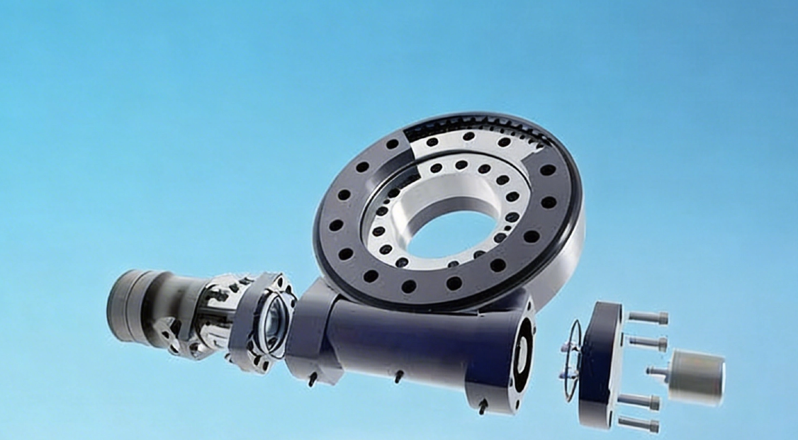
Torque Path: From Input Shaft Through Worm Gear to the Slewing Ring
Torque moves in a straight chain. Each stage changes the speed and force, and each stage sees a different kind of load. The table below follows the path in a typical single-worm unit, such as a worm gear slew drive.
| Stage | What happens | Load it carries | What to check |
|---|---|---|---|
| 1. Input shaft (motor or hydraulic motor) | Supplies rotation at high speed and low torque | Torque only; small bearing reactions at the worm shaft ends | Motor interface, keyway or spline, shaft end loads |
| 2. Worm shaft | Converts shaft rotation into tangential force on the gear teeth | Tooth contact force plus axial thrust along the worm axis | Thrust bearing arrangement, lubrication, backlash setting |
| 3. Gear teeth on the slewing ring | Reduce speed and multiply torque; push the ring around | Tangential tooth load from steering resistance | Tooth strength, contact pattern, wear over time |
| 4. Slewing ring raceways | Guide rotation and keep the two rings concentric | Axial, radial and overturning loads from the structure | Raceway type, rated static and dynamic capacity |
| 5. Mounting flanges and bolts | Transfer loads to the frame and the rotating part | All structural loads, as bolt tension and shear | Flange flatness, bolt grade, preload |
The key point is stage 3 versus stage 4. The gear teeth only see the force needed to overcome steering resistance, such as friction, inertia and any side push on the wheel or platform. The raceways see everything else.
How the worm ratio changes the picture
A high worm ratio gives a large torque multiplication from a small motor. It also lowers speed and efficiency. A single worm drive often gives slow, smooth steering, but friction losses mean more input power for the same output torque.
Efficiency also drives self-locking. Many worm sets resist back-driving because friction in the mesh is high compared with the lead angle. This helps hold a position with the motor off. It is not a guarantee, so for vibration, shock or safety-critical holding, a brake is still the usual design choice.
Axial, Radial and Overturning Loads: What Steers and What Does Not
Three structural loads act on the bearing. None of them should pass through the worm. The table shows where each one goes and whether it affects steering torque.
| Load type | Direction | Carried by | Effect on steering torque |
|---|---|---|---|
| Axial | Along the rotation axis (weight, vertical force) | Raceways and rolling elements | Raises rolling friction, so torque to start rotation goes up |
| Radial | Sideways, across the axis (lateral push, wind, wheel side force) | Raceways; gear housing supports the ring | Can shift gear mesh if clearance is too large |
| Overturning moment | Tipping force from an offset load | Opposite sides of the raceway, one side in compression, one unloaded | Largest influence on bearing life; also can distort the ring and change backlash |
Overturning moment is the one that surprises people. A small weight placed far from the axis creates a large tipping force. The bearing size is usually set by this moment, not by the vertical weight.
The worm only sees the steering resistance. In practice, though, structural loads still change the steering torque you need. Heavy axial load increases rolling friction, and moment load can tilt the ring slightly. That is why we size the motor with margin on top of the pure steering calculation.
Request Your Custom Slew Drive or Bearing Spec
Tell us your load, speed, and environment — receive a tailored 100–5000 mm slewing drive or slewing bearing proposal with 3D drawings within 24 hours.
How the Key Parameters Interact
No single number tells you if a drive will work. Several parameters push on each other. Here are the ones that matter most in concept design.
- Raceway type and moment capacity. A larger raceway diameter handles a bigger tipping moment, but it adds weight and cost. It fits platforms with a tall or offset load. It does not help if the mounting structure is too flexible to use that capacity.
- Single worm versus double worm. A double worm slew drive shares tooth load across two mesh points. That suits higher steering torque or reduced backlash needs. It adds one more shaft to seal and align, so it is not a default upgrade for light duty.
- Backlash and precision. Lower backlash gives tighter positioning, but it also raises mesh friction and wear if alignment is off. Specify the precision your control loop actually needs rather than the tightest value available.
- Sealing and environment. Our slew drives are available with protection up to IP66 and anti-corrosion ratings up to C4H. Higher sealing adds seal drag, which slightly raises starting torque. For dusty, wet or coastal sites, that trade is usually worth it.
- Material. Alloy steel, forged alloy steel, ductile cast iron and stainless steel each fit different load, speed and corrosion conditions. Choose by working condition, not by price alone.
Do not compare ratings from different sources as if they were equal. Static capacity, dynamic capacity and holding torque are measured under different assumptions. Ask which condition each number refers to.
Common Misunderstandings That Change the Design
After 30 years in power transmission design, I see the same errors repeat in early concept work. These are the ones that cost the most to fix later.
- "The motor carries the weight." It does not. The motor only supplies steering torque. Sizing it for the structural load wastes cost and space.
- "Self-locking means no brake needed." Self-locking depends on the friction state of the mesh. Vibration or shock can reduce it. For safety-critical holding, add a brake.
- "A bigger bearing is always safer." A larger ring needs a stiffer mounting structure. On a flexible frame, extra capacity is not usable.
- "Vertical load sets the size." Offset load and overturning moment usually decide it.
To verify a supplier's claim, ask for the load rating basis, the raceway type, the gear tooth data and the inspection method. Evidence from dimensional inspection can confirm geometry, but only a load test shows how the unit behaves under moment. We run CMM three-coordinate inspection and dynamic load testing, described on our slew drive quality control page. Our ISO 9001:2015 certified facility keeps these records available on request.
Real Applications: Where Steering Load Control Matters
Real projects show how the load split works in the field. These are cases from our customers, described within their stated context.
- Heavy-duty wheel steering, Houston, Texas. An engineering machinery manufacturer ordered 150 units of WED17-104-25HR double worm drives. Wheel steering means high side forces and shock, so shared tooth load across two worms suits the duty. See our WED slew drive range.
- Forestry grapple machines, British Columbia. A forestry equipment manufacturer bought 30 units of WED14-86-25BHR.5 with precision of 0.13° or better. Grapple loads are offset and variable, so moment capacity and low backlash both matter.
- Port cranes, South Korea. A port equipment manufacturer placed a repeat order for 20 units of WEA9-62-25HR single worm drives. The specification called for tracking precision within 0.15°, IP65 sealing and self-locking.
The three cases use different drive types for different steering loads. That is the main lesson: match the gear arrangement to the torque and shock pattern, and match the bearing to the moment.
What to Prepare Before Requesting a Quote
At the concept stage, a few inputs let an engineer give you a useful recommendation. Without them, any specific model is a guess.
- Axial load, radial load and overturning moment, with the load center distance from the axis
- Required steering torque, rotation speed and duty cycle
- Positioning accuracy or backlash target
- Holding requirement: static only, or with vibration and shock
- Environment: dust, water, salt, temperature range
- Mounting frame stiffness and flange flatness you can achieve
- Drive input: electric or hydraulic motor, and the interface
Standard products start at an MOQ of 1 set, and customized products at 5 sets. Sample orders are welcome for testing. We typically send a technical proposal within 24 hours, and the standard production cycle is 9 days. If the standard range does not fit your envelope, a customized slew drive can change the ratio, interface or sealing.
Our 2-year extended quality warranty covers confirmed manufacturing defects with free replacement, and our engineers respond to technical questions within 48 hours. If you are comparing the bearing side on its own, start with our slewing bearing range, then review how the drive and ring fit together in your design.
Request Your Custom Slew Drive or Bearing Spec
Tell us your load, speed, and environment — receive a tailored 100–5000 mm slewing drive or slewing bearing proposal with 3D drawings within 24 hours.
 WhatsApp

 +8613903880726