


Force Conditions Analysis of Spur Gear Slew Drives During Operation
What is Spur Gear Slew Drive?
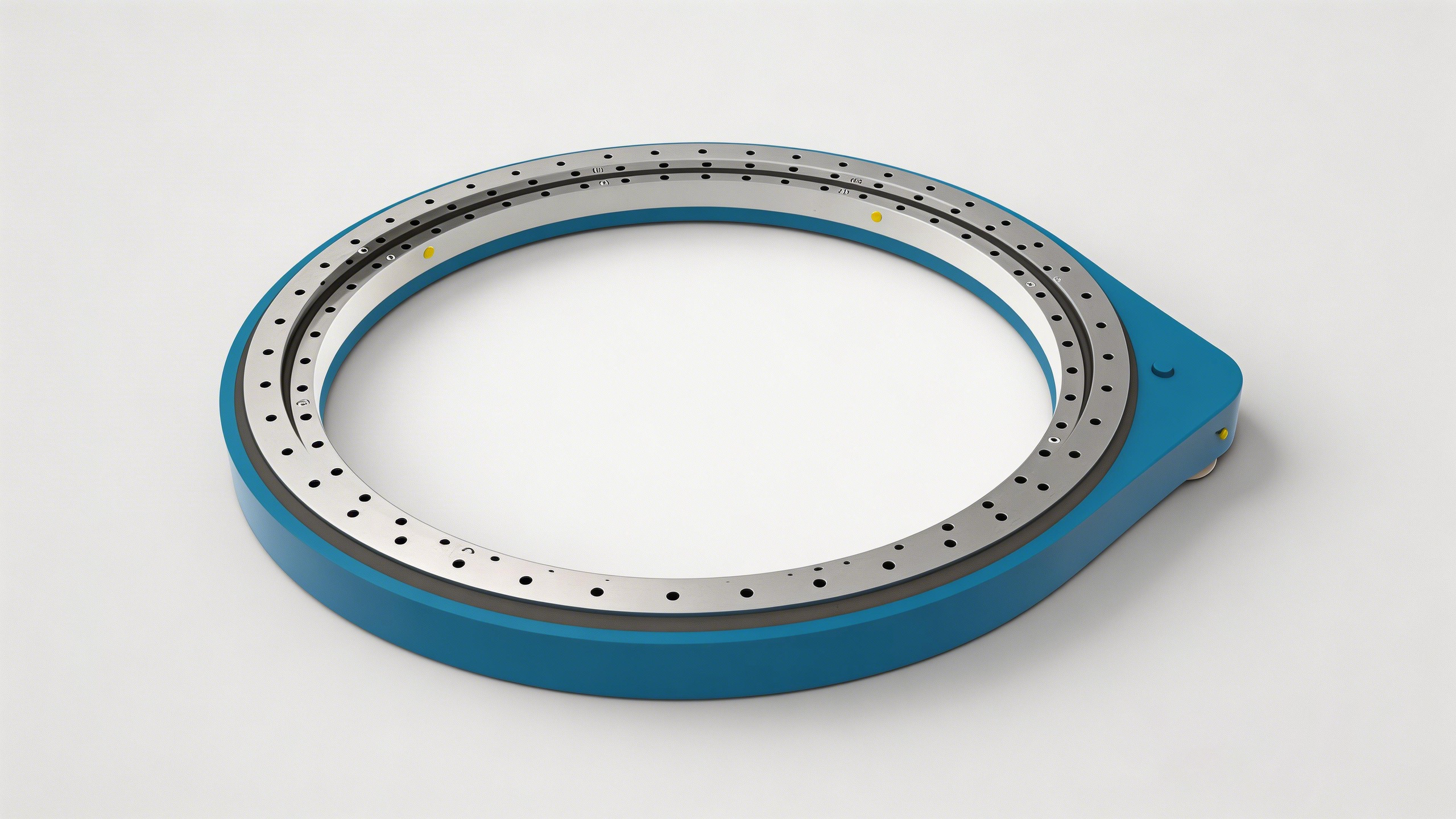
A spur gear slew drive is a compact, high-capacity rotating device. It integrates a slewing bearing, a drive pinion, a housing, and often an accessory drive (like a motor) into a single ready-to-mount unit.
The core of the drive is the slew drive itself, which uses a large-diameter slewing bearing with external or internal spur gear teeth. The pinion (a small spur gear) meshes directly with this large ring gear. This simple and robust design allows the slew drive to efficiently handle heavy loads while providing precise rotational movement.
How Does a Spur Gear Slew Drive Work?
The working principle of a spur gear slew drive is straightforward and highly effective.
Typically, the inner ring of the slew drive's bearing is fixed to a base (like a vehicle chassis or stationary frame). The outer gear ring is bolted to the rotating platform (like a crane arm or solar panel array).
The power transmission process:
A motor (electric or hydraulic) provides rotational power.
This power drives the small pinion gear to rotate.
The pinion's teeth, which are straight-cut, push against the teeth of the large gear ring on the slewing bearing.
This meshing action forces the outer ring of the slew drive, along with the attached load, to rotate.
Because the pinion and ring gear teeth are straight (parallel to the axis), there is no axial force generated at the gear mesh itself, making the motion smooth and the thrust load management simpler for the bearing.
Applications of Spur Gear Slew Drives
Spur gear slew drives are preferred in applications requiring high precision, high rotational speeds, or when the primary loads are axial and radial rather than high tilting moments with heavy axial thrust. Common applications include:
Automated machinery: Indexing tables, robotic arms, and packaging equipment.
Renewable energy: Solar tracking systems (single-axis trackers).
Material handling: Small conveyor turntables and lift platforms.
Construction attachments: Auger drives and small crane winches.
Key Force Conditions and Analysis of Spur Gear Slew Drive
Spur gear slew drives operate under combined loading conditions—axial, radial, and tilting moment—during rotation, with the pinion driving the outer gear ring to rotate a turntable. Key forces analyzed during operation include tangential, radial, and axial loads, which, along with lubrication, impact gear tooth stress, contact fatigue, and wear.During operation, a spur gear slew drive is subjected to complex and combined loads. Understanding these forces is critical for correct selection and long service life.
1.Types of External Loads
The working load on the slew drive is typically broken down into three basic vectors:
Axial Load (Fa): The force acting parallel to the rotation axis. In horizontal installations (e.g., a rotary table), this is usually the weight of the load. All rolling elements in the raceway share this load equally.
Radial Load (Fr): The force acting perpendicular to the rotation axis, pushing the ring sideways. In vertical installations (e.g., a hanging pendant arm), this is the dominant force. Only a portion of the rolling elements carry this load at any given time.
Tilting Moment (Mk): The overturning force. It is the result of a radial force applied at a distance from the mounting surface (lever arm). This force creates a "pressure" on one side of the raceway and a "lifting" force on the opposite side. The rolling elements on both sides resist this moment, but only some carry the full load.
In reality, these three loads rarely occur in isolation. A typical operating cycle involves all three acting simultaneously. The specific ratio of Fa, Fr, and Mk defines the application difficulty.
2. Forces at the Gear Mesh
Unlike helical gears, spur gears have zero helix angle. This is the defining factor of their force condition.
Normal Force (Fn): This is the total force acting perpendicular to the tooth surface at the contact point.
Tangential Force (Ft): This is the primary force that causes rotation. It acts along the pitch circle tangent. Torque = Ft × Radius.
Radial Force (Fr): This force pushes the pinion away from the ring gear. It acts towards the center of the gear.
Critical Distinction: Because the teeth are straight, there is zero axial force (Fa) generated at the gear mesh. This means the slew drivehousing and the bearing do not need to manage internal gear thrust, simplifying the internal stress flow.
3. Internal Raceway Stress
The external loads (Fa, Fr, Mk) are transferred through the gear teeth and mounting bolts into the slew drive bearing raceway.
Contact Stress: The rolling elements (balls or rollers) press into the raceway. This stress (Hertzian stress) is extremely high and localized. The depth of the hardened layer, raceway curvature, and rolling element size are designed specifically to prevent pitting or Brinelling under this cyclic stress.
Load Distribution: Not all rolling elements share the load equally. The tilting moment causes a sinusoidal load distribution around the ring. The analysis must identify the maximum loaded rolling element, as this is the point where failure is most likely to initiate.
Common Analysis Methods
To accurately predict how the slew drive will behave under force, engineers use several methods:
1. Static Load Capacity Analysis
This is the fundamental selection method. The slew drive is rated by a Static Load Capacity Curve.
Method: The specific combination of axial load (Fa) and tilting moment (Mk) is plotted on the manufacturer's curve.
Goal: To ensure the operating point falls below the curve, providing a specific safety factor (fs). This prevents plastic deformation of the raceway.
2. Dynamic Load Rating & Life Calculation
Since slew drives often oscillate rather than rotate continuously, standard bearing life formulas (L10) are adapted.
Method: The equivalent dynamic load is calculated based on the weighted average of the fluctuating loads during the duty cycle.
Goal: To predict the total service life (in revolutions or hours) before material fatigue occurs on the raceways or gear teeth.
3. Finite Element Analysis (FEA)
For critical or highly stressed applications, FEA is used.
Method: A 3D model of the slew drive housing, bearing, and gear is simulated. The software maps stress distribution, deformation, and contact pressure.
Goal: To identify stress "hot spots" in the housing casting or bolt connection areas that basic calculations might miss.
4. Gear Strength Analysis (AGMA/ISO)
The pinion and ring gear teeth are analyzed as machine elements.
Method: Standards like AGMA (American Gear Manufacturers Association) or ISO 6336 are applied.
Goal: To check bending strength (preventing tooth breakage at the root) and contact durability (preventing pitting on the tooth flank).
Operational Challenges Faced When Analyzing the Force
Analyzing the force of a spur gear slew drive is complex. Several challenges often arise:
1. Combined Load Complexity
The simultaneous application of axial load, radial load, and tilting moment creates a non-linear stress distribution in the raceway. It is difficult to determine exactly how much of the radial load is being carried versus the tilting moment. Simplified 2D calculations often underestimate the stress on the corner of the raceway.
2. Mounting Structure Stiffness
A common oversight is assuming the mounting structure (the base and the turntable) is infinitely rigid.
Challenge: If the mounting surface is too flexible, it deforms under load. This deflection breaks the flatness of the slew drive's mounting plane.
Result: Additional internal stresses are introduced, causing "edge loading" on the raceway and bolt loosening.
3. Load Spectrum Accuracy
To calculate fatigue life, we need to know how often the machine lifts heavy loads versus light loads.
Challenge: In many custom applications, the exact duty cycle is unknown during the design phase. Incorrect assumptions lead to either over-engineering (high cost) or premature failure.
4. Gear Mesh Alignment
Spur gears are sensitive to misalignment.
Challenge: Heavy radial loads can deflect the pinion shaft or the ring gear. If the gears twist out of parallel alignment, the tooth contact becomes uneven. Instead of a full line contact across the face width, the load concentrates on the edge of the tooth.
Result: Gear tooth breakage or accelerated wear.
5. Thermal Effects
In high-speed applications, friction generates heat.
Challenge: Heat causes the gear teeth to expand. If the thermal expansion gap is not calculated correctly, the slew drive can experience thermal lockup or excessive backlash increase.
LyraDrive: Customised Spur Gear Slew Drive Solutions
At LyraDrive, we understand that every application has a unique "force fingerprint." As a specialized manufacturer of slew drives and slew bearings, our engineering philosophy focuses on matching the internal geometry precisely to your external load conditions.
We offer customized solutions including:
Raceway Optimization: Adjusting hardening depth and raceway curvature specifically for your dominant load (axial-heavy vs. moment-heavy).
Gear Cutting: Precision spur gear cutting to achieve your desired backlash specifications (from zero-backlash for precision indexing to standard backlash for dirty environments).
Integrated Design: Custom housings and seal arrangements to protect the internal force components from your specific environmental contaminants (dust, water, chemicals).
If your project requires a spur gear slew drive that is designed based on a deep analysis of its actual working forces—not just a standard catalog item—contact LyraDrive. We engineer the rotation behind your performance.