


Spur Gear Design Considerations in Slew Drives
What is Spur Gear Slew Drive
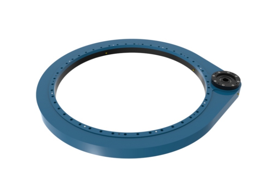
Spur Gear Slew Drive denotes a rotary motion system where a straight-toothed pinion directly engages gear teeth integrated into a slewing ring bearing’s inner or outer race. This configuration achieves over 95% mechanical efficiency through pure rolling contact dominance, outperforming worm gear alternatives in energy conservation. Characterized by manufacturing simplicity, cost-effectiveness, and superior radial load capacity, these drives require external braking due to negligible self-locking capability. They excel in solar tracking systems, material handling conveyors, and indexing applications where operational speeds exceed 20 RPM.

Critical Gear Design Factors in Spur Gear Slew Drives
Meshing Accuracy and Kinematic Integrity
Achieving smooth power transmission demands strict adherence to gear meshing fundamentals. Tooth profiles must conform to the fundamental law of gearing to maintain constant velocity ratios between shafts. Modern designs utilize 20° pressure angle involute profiles which deliver conjugate action with linear contact paths. Precision manufacturing to AGMA Class 8 standards (ISO 1328 equivalent) controls profile deviations under 15μm and cumulative pitch errors below 25μm. Maintaining a minimum contact ratio of 1.2 prevents engagement discontinuity through strategic addendum modifications not exceeding 0.4 times the module. Tooth tip relief of 0.01-0.02mm depth eliminates edge loading while micro-crowning (0.015mm/mm) compensates for mounting deflections. Quasi-helical designs incorporate helix angle modifications under 0.5° to dampen vibration.
Dual-Mode Fatigue Resistance Engineering
Gear longevity hinges on simultaneous optimization against surface and root failures. Surface durability requires Hertz contact stress calculations with material elasticity coefficients. For steel-on-steel meshing, maximum contact pressure must stay below 1,500 MPa through case hardening achieving 58-62 HRC surface hardness with case depths exceeding 1.2mm. Tooth root bending fatigue follows enhanced Lewis equation principles, demanding form factor optimization between 2.8-3.2 for pinions with 17-25 teeth. Critical stress correction factors above 1.7 are maintained through root radius optimization greater than 0.38 times the module. Shot peening introduces 400 MPa compressive stresses to delay crack initiation. Finite element analysis validates fillet stresses remain under 300 MPa with safety factors exceeding 1.5 against bending fatigue.
Strategic Transmission Ratio Selection
Intelligent ratio design prevents localized wear patterns and vibration amplification. Prime-numbered ratios ensure uniform tooth engagement distribution across all gear teeth. Ratios like 19:95 avoid repetitive meshing cycles that accelerate pitting. Decimal ratios such as 18.75:1 require compound gearing or planetary pre-stages. Tooth count parity rules dictate optimal pairings: odd-numbered pinions with odd-numbered ring gears represent ideal configurations. Even-to-odd combinations remain acceptable while even-to-even pairings create high-risk scenarios for resonance and accelerated wear. These principles extend service life by over 30% in high-cycle applications.
Undercutting Prevention and Root Optimization
Conventional 17-tooth minimums are reduced to 15 teeth through advanced design techniques. Positive profile shifting between +0.3 to +0.6 combined with 0.3 module tip reduction on mating gears eliminates interference. Trochoidal root profiles increase clearance while maintaining strength. Dedendum depths extend to 1.25 times the module with polished root surfaces achieving Ra ≤ 0.8μm roughness. Metallurgical solutions include vacuum-degassed 20MnCr5 steel subjected to 930°C carburization followed by cryogenic treatment at -196°C to transform retained austenite. These measures permit compact designs while maintaining bending fatigue resistance.
Spur Gear Slew Drive Characteristics
Radial load dominance enables handling of overturning moments 2.5 times greater than equivalent worm drives. Operational speeds range from 10-150 RPM, significantly higher than worm drive limitations. Thermal management requires minimal intervention due to 95%+ efficiency. Backlash control demands AGMA Class 8+ manufacturing with positional accuracy under 5 arc-minutes. Compact architecture reduces installation footprints by 15-20% versus planetary alternatives. Maintenance accessibility allows gear inspection without full disassembly.
Industrial Applications of Spur Gear Slew Drive
Solar tracking systems leverage the efficiency for single-axis panel positioning. Conveyor sorting turntables utilize the radial load capacity for heavy payload rotation. Packaging machinery indexes containers at speeds exceeding 60 cycles/minute. Medical imaging gantries require the smooth motion for precision scanning. Aerospace test rigs benefit from the minimal heat generation in vacuum environments. Light infrastructure applications include rotating billboards and stage machinery.
Price Determinants of Spur Gear Slew Drive
Slewing bearing size and dynamic moment ratings drive 40-50% of total cost. Gear quality specifications including AGMA class, case depth over 1.2mm, and grinding precision add 20-30%. Housing complexity from integrated mounting features increases machining expenses. Input shaft connections using DIN 5482 splines cost 18% more than standard keyed shafts. IP66 sealing with triple-lip seals adds 12-15% over basic protection. Custom ratios requiring non-standard tooling incur 25% premiums. Order volumes above 50 units activate 20% economies of scale. Third-party certifications like ISO 9001 and CE contribute 8-10% to administrative overhead.
Supplier of Spur Gear Slew Drive
LYRADRIVE delivers AGMA Class 10 spur gear slew drives featuring cryogenically treated 20MnCr5 gearing with optimized root profiles. Their solar-tracker validated designs achieve 97% efficiency with 0.3 module tip relief standardization. Custom ratio configurations avoid resonance through prime-number tooth counts, supported by FEA validation reports for critical applications.