


Slew Drive Installation Guide: Key Procedures and Precautions
What is a Slew Drive?
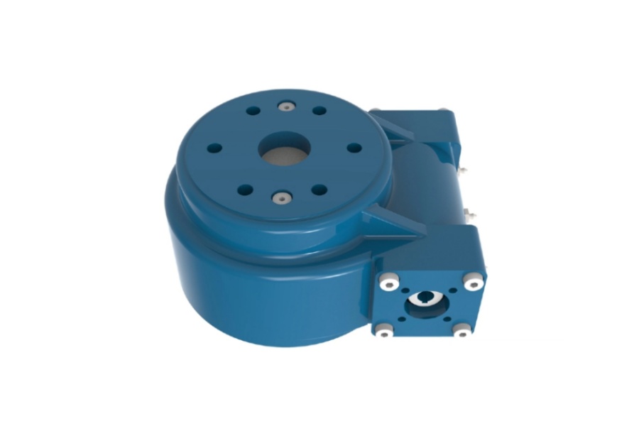
Slew Drive, also known as a slewing ring drive or slewing bearing drive, is a highly integrated rotational mechanism. It combines a slewing bearing (a large-diameter rolling-element bearing capable of handling axial, radial, and moment loads) with an internal gear or pinion, a drive motor (typically electric or hydraulic), and often a gear reduction unit like a planetary gearbox. This compact assembly delivers high-torque rotational output in a single axis, enabling precise and controlled rotation of heavy loads. Slew drives are fundamental components in applications requiring robust, reliable, and controlled slewing motion.

How to Install a Slew Drive and Key Considerations
Proper installation is paramount for the performance, longevity, and safety of a slew drive. Mistakes during installation can lead to premature wear, excessive noise, increased friction, binding, or catastrophic failure. Follow these critical steps and precautions:
I. Pre-Installation Preparation
Thoroughly Clean Mounting Surfaces: Clean both the slew drive mounting surfaces and the corresponding mating surfaces on the host structure meticulously. Remove all paint residue, weld spatter, burrs, dirt, grease, and any other foreign matter. Crucially, also remove any corrosion protection coating present on the slew drive's mounting surfaces. Critical Considerations: Prevent any cleaning liquids from seeping into the slew drive's internal seals. Avoid using cleaning materials that could corrode the slew drive's seals.
Lubricate the Slew Drive: While slew drives are lubricated at the factory, re-lubrication before initial operation is essential, especially if the unit has been stored for an extended period. Ensure the slew drive is fully lubricated. Critical Considerations: Use ONLY the specific grease type and grade explicitly specified in the slew drive's delivery documentation or installation manual. Using incorrect lubricant can severely damage internal components.
Select Appropriate Mounting Hardware:
Use bolts of the exact size, quantity, thread type, and quality grade (e.g., ISO property class 10.9) mandated in the slew drive's installation manual.
Adhere strictly to the specified clamp length ratio (clamp length divided by bolt diameter), typically requiring a minimum ratio ≥5 and a maximum ratio ≤10. This ensures proper bolt stretch and clamping force.
NEVER use bolts with a full-length threaded shank within the clamped area. The unthreaded shank section provides uniform clamping force.
Non-compliance compromises bolt connection integrity, function, service life, and safety.
If interface pressure limits could be exceeded, use hardened washers of appropriate size and strength grade under the bolt head and nut.
ALWAYS use new bolts, nuts, and washers. Reusing old hardware is unsafe and unreliable.
Determine Correct Tightening Torque:
Mounting bolts must be tightened to the precise preload force specified in the manual to ensure secure fixation without damaging the bolt or the slew drive structure.
Apply a thread-locking compound (e.g., Loctite) to bolt threads if specified or recommended in the manual to prevent loosening.
NEVER use split pins (cotter pins), lock washers, or similar non-preload locking devices in place of correct torque or thread locker.
If washers are used, ensure they match the strength grade of the bolts.
II. Installation Process
Position and Bolt the Slew Drive:
Lightly lubricate bolt threads (unless using a locking compound) to ensure consistent friction and accurate torque application.
Tighten bolts in a star-pattern sequence (crossing diagonally) in three distinct stages: typically first to 30% of final torque, then to 80%, and finally to 100% of the specified torque. Include washers during tightening.
Repeat this multi-stage, star-pattern tightening procedure for the opposing ring (if bolted on both sides).
Critical Consideration: When using hydraulic tensioning tools, the applied preload force must NOT exceed 90% of the bolt's yield stress.
Measure Tilt Clearance and Gear Backlash:
Tilt clearance (axial play) naturally increases as the bearing raceways wear. To establish a baseline for future monitoring, perform precise tilt clearance measurements immediately after installation, BEFORE the slew drive enters service. The allowable increase in tilt clearance during service is typically limited to 1.5 - 2.0 mm; consult the specific slew drive documentation for exact tolerances.
Gear backlash (the play between the pinion and the slew drive gear) is a critical indicator of gear wear. Permissible backlash levels vary significantly depending on the slew drive type, size, and application. Refer to the manufacturer's specifications for acceptable ranges.
Crucially: Record all initial measurements meticulously (tilt clearance, backlash). All subsequent measurements for comparison must be taken at identical measurement points, under identical load conditions, with the bearing rings in the same relative position, and following the exact same sequence. For pure axial or radial load scenarios, tilt clearance should be verified by applying an additional tilting load.
Conduct Operational Testing:
Rotate the installed slew drive several full revolutions manually or at low speed. Correct installation should result in smooth, uniform rotation without binding or catching.
Check for any unusual vibrations, noise, or jerkiness during rotation. Factors like structural deformation under load or external forces can influence friction torque.
If possible, perform further test runs under the intended full operational load to verify performance under working conditions.
Critical Consideration: After the initial operational test run, re-check the tightening torque of ALL mounting bolts. Initial settling can sometimes cause slight loosening.
Key Characteristics of Slew Drives
Slew drives offer a unique combination of features that make them indispensable for demanding rotational applications:
High Load Capacity: Engineered to handle substantial combined loads (axial, radial, and tilting moments) simultaneously within a single compact unit.
Integrated Design: Combines bearing, gearing, sealing, and often the drive motor and reduction into one pre-assembled, pre-tested unit, simplifying system design and assembly.
Precision Rotation: Capable of providing highly controlled and accurate rotational positioning, essential for applications like solar tracking or crane operation.
High Stiffness and Rigidity: Designed to minimize deflection under heavy loads, ensuring positional accuracy and system stability.
Robust Construction: Manufactured from high-strength materials with hardened raceways and gears for exceptional durability and long service life in harsh environments.
Compactness: Delivers high torque and load capacity relative to its physical size, saving valuable space in machinery design.
Sealed and Lubricated: Equipped with effective sealing systems to protect internal components from contamination and retain lubricant, often featuring lubrication points for maintenance.
Versatile Mounting: Typically designed with standardized bolt patterns and mounting configurations for ease of integration.
High Efficiency: Modern designs, especially with optimized gear meshes (like helical or epicyclic), offer excellent power transmission efficiency.
Primary Applications of Slew Drives
The unique capabilities of slew drives make them critical components across numerous industries:
Renewable Energy: Solar Trackers (single-axis and dual-axis), Wind Turbines (pitch and yaw control).
Construction Machinery: Mobile Cranes, Tower Cranes, Concrete Pumps, Excavators, Aerial Work Platforms (boom lifts).
Material Handling: Stacker/Reclaimers, Ship-to-Shore Cranes, Rail-mounted Gantry Cranes, Rotating Conveyors.
Industrial Automation: Robotic Welding Arms, Large Turntables, Indexing Tables, Rotary Furnaces, Mixers.
Defense and Aerospace: Radar Antennas, Missile Launchers, Gun Turrets, Satellite Communication Dishes.
Mining: Bucket Wheel Excavators, Draglines, Tunnel Boring Machines.
Medical: Heavy-duty medical imaging equipment (CT, MRI gantries).
Agriculture: Large Irrigation Systems (center pivots, linear moves).
Marine: Deck Cranes, Winches, Propulsion Azimuth Thrusters.
Factors Influencing Slew Drive Price
The cost of a slew drive varies significantly based on several key factors:
Size and Load Capacity: Larger diameter slew drives capable of handling higher axial loads, radial loads, and tilting moments inherently require more material and complex manufacturing, increasing cost substantially.
Gear Type and Ratio: The complexity of the internal gearing (spur vs. helical), the gear reduction ratio, and the precision required significantly impact machining time and cost. Planetary gearboxes integrated into the drive add cost but offer high ratios in compact sizes.
Material Specifications: The grade and quality of steel used for rings, gears, and rolling elements (balls or rollers) directly affect durability, load capacity, and price. Special materials (e.g., for corrosion resistance) add cost.
Manufacturing Precision and Tolerances: Slew drives are precision components. Tighter manufacturing tolerances for raceways, gears, and overall geometry ensure smooth operation and longevity but require more advanced machining and quality control, raising the price.
Sealing and Environmental Protection: The complexity and effectiveness of sealing systems (e.g., multi-lip seals, special elastomers) needed for harsh environments (dust, water, chemicals, extreme temperatures) increase cost.
Bearings and Rolling Elements: The type (ball vs. roller), size, quantity, and quality grade of the rolling elements influence load capacity, stiffness, and cost. Cross roller designs offer high stiffness but can be more expensive than four-point contact ball designs for certain loads.
Integrated Components: Whether the slew drive is supplied as a bare unit, includes an integrated gearbox, or comes pre-assembled with a specific motor (electric or hydraulic) greatly affects the overall price.
Lubrication System: Complexity of lubrication channels, type of fittings, and requirements for automatic lubrication systems add to the cost.
Certifications and Testing: Slew drives requiring specific industry certifications (e.g., DNV-GL, ABS, CE) or undergoing rigorous load testing and documentation will have a higher price point.
Brand Reputation and Quality: Established manufacturers with proven reliability and extensive support networks often command premium pricing compared to generic alternatives.
Order Quantity and Customization: Standard catalog items ordered in volume typically cost less per unit than highly customized solutions or single-unit purchases.
Slew Drive Supplier
LYRADRIVE is a recognized manufacturer specializing in the design and production of high-performance slew drives for demanding industrial applications. They focus on engineering robust solutions capable of handling significant combined loads while ensuring precision and reliability. LYRADRIVE offers a range of standard slew drive configurations but also possesses strong capabilities in developing custom-engineered solutions tailored to specific customer requirements, load profiles, and environmental conditions. Their commitment to quality manufacturing processes and rigorous testing helps ensure their slew drives meet the performance and durability expectations of sectors like renewable energy, heavy machinery, and automation. For detailed specifications, technical support, or custom project inquiries, contacting LYRADRIVE directly to discuss application needs and request current documentation is recommended.