


Reducing Gear Noise in Slewing Bearings
What is Slewing Bearing
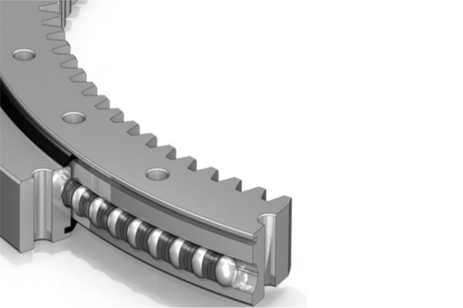
Slewing Bearing, also known as a slewing ring, turntable bearing, or swing bearing, is a large-diameter rolling-element bearing specifically designed to handle combined loads (axial, radial, and tilting moments) while enabling rotational movement between two structures. Unlike standard bearings, slewing bearings are integral machine components, often featuring integrated gear teeth (internal or external) on one of their rings. These teeth mesh with a pinion gear driven by an electric or hydraulic motor, providing the controlled rotation essential in countless applications. Their robust construction allows them to act as both a load-bearing element and a rotational drive mechanism.

How to Reduce Gear Noise in Slewing Bearings
Gear noise, often perceived as whining, grinding, or clattering, is a common concern in slewing drive systems. Excessive noise not only indicates potential problems but also contributes to operator fatigue and environmental pollution. Addressing noise requires a multi-faceted approach focusing on design, manufacturing, installation, and operation:
Optimize Gear Accuracy:
Principle: Precise tooth geometry ensures smooth meshing, minimizing impact and vibration at the tooth contact point, which are primary noise sources.
Action: Specify and manufacture the gear teeth (on the slewing ring) and the mating pinion to a high degree of accuracy. For slewing bearings, gear quality classes of AGMA 7 to 9 or ISO 7 to 8 are typically recommended for noise reduction. Higher rotational speeds demand higher precision (e.g., AGMA 7/ISO 7 for pinion speeds above 20 m/s pitch line velocity).
Considerations: Precision grinding of gear teeth after hardening achieves superior accuracy and surface finish compared to hobbing alone. Ensure both the slewing ring gear and the pinion are manufactured to compatible tolerance grades.
Refine Gear Tooth Profile and Modifications:
Principle: Minor deviations from a perfect involute profile can compensate for deflections under load and manufacturing tolerances, promoting smoother load transfer and reducing transmission error (a major noise contributor).
Action: Implement profile modifications (tip and root relief) and lead crowning on both the slewing ring gear and the pinion. Profile relief prevents edge loading at the tips and roots of teeth. Lead crowning accommodates misalignment and shaft deflection, ensuring contact occurs in the central portion of the tooth face.
Considerations: The specific type and amount of modification require expert calculation based on expected loads, deflections, and bearing size. Collaboration with gear specialists is crucial.
Achieve Proper Gear Alignment:
Principle: Misalignment between the pinion shaft axis and the plane of the slewing ring gear causes uneven load distribution across the tooth face, leading to localized high stress, rapid wear, and increased noise.
Action: Ensure extremely precise alignment during installation. Use laser alignment tools or precision dial indicators to verify:
Parallelism: Pinion shaft axis parallel to the slewing bearing axis.
Center Distance: Correct distance between pinion shaft center and slewing bearing centerline.
Backlash: Proper initial gear backlash as specified by the manufacturer.
Considerations: Account for potential structural deflection under load during alignment. Use rigid mounting structures for both the bearing and the drive motor/gearbox. Re-check alignment periodically during service.
Implement Effective Lubrication:
Principle: Adequate lubrication forms a protective film between meshing teeth, reducing friction, wear, and the direct metal-to-metal contact that generates noise. It also dampens vibrations.
Action:
Use a high-quality, extreme-pressure (EP) gear lubricant specifically formulated for slow-speed, high-load applications. Viscosity should match the operating temperature range.
Ensure lubrication reaches the meshing point effectively. Centralized automatic lubrication systems are highly recommended for consistent delivery.
Maintain correct lubrication intervals based on operating conditions (duty cycle, temperature, contamination risk). Over-lubrication can cause churning losses and heat; under-lubrication leads to increased friction and wear noise.
Keep lubricant clean. Effective seals are vital to prevent abrasive contaminants from entering the gear mesh.
Considerations: In very noisy applications, specially formulated "quiet" gear oils with friction modifiers or sound-dampening additives may be beneficial.
Control Operational Dynamics:
Minimize Shock Loads & Rapid Direction Changes:
Principle: Sudden impacts or frequent, abrupt reversals cause severe dynamic loading on gear teeth, inducing high-frequency vibrations and impact noise ("clatter").
Action: Implement controlled acceleration/deceleration ramps in drive controls. Avoid sudden starts, stops, and direction reversals where possible. Use shock-absorbing components in the drive train if impacts are unavoidable.
Avoid Resonance:
Principle: When the natural frequency of the structure or drive train coincides with the excitation frequency from the gear mesh or motor, resonant amplification occurs, producing loud, high-pitched whining or howling.
Action: Identify critical speeds that induce resonance. Modify operating speeds to avoid these critical ranges. If speed change isn't feasible, consider structural stiffening, adding damping materials, or changing the mass distribution to shift the natural frequency.
Manage Load Fluctuations: Smooth out load variations where possible, as rapid load changes can excite vibrations.
Enhance Surface Finish:
Principle: A smooth tooth surface reduces friction and minimizes localized high points ("asperities") that cause noise during initial run-in and under load.
Action: Specify a fine surface roughness (Ra) for the gear flanks. Precision grinding inherently provides a better finish than hobbing. Superfinishing processes can further reduce Ra values significantly.
Considerations: A smoother finish also improves lubricant film formation. Ensure surface finish specifications are maintained during manufacturing and not degraded by improper handling or corrosion.
Ensure Adequate Gear Backlash:
Principle: Insufficient backlash causes jamming and excessive preload on the teeth, leading to high friction, rapid wear, and noise. Excessive backlash causes impact loading as teeth engage.
Action: Set the initial backlash precisely according to the manufacturer's specifications during installation. Account for thermal expansion (operating temperature vs. installation temperature) and expected wear over time. Use adjustable pinion mounts to facilitate setting and potential future readjustment.
Select Appropriate Gear Type (Design Phase):
Principle: Helical gears generally operate more smoothly and quietly than spur gears due to gradual tooth engagement.
Action: Where noise is a critical concern and design allows, specify helical teeth on both the slewing ring and pinion instead of spur teeth. The helix angle promotes smoother load transfer across multiple teeth simultaneously.
Considerations: Helical gears introduce axial thrust loads that the bearing and structure must accommodate. Design complexity and cost are higher than spur gears.
Key Characteristics of Slewing Bearings
Slewing bearings possess distinct features enabling their diverse applications:
Combined Load Capacity: Engineered to simultaneously support significant axial, radial, and tilting moment loads.
Integrated Rotation: Combines load support and rotational motion transmission (via gears) in a single unit.
Large Diameter: Manufactured in diameters ranging from several centimeters to over 15 meters.
Robust Construction: Typically made from high-strength, hardened alloy steels.
Gear Options: Available with internal or external gear teeth (spur or helical).
Sealing: Incorporate sealing systems (labyrinth, lip seals) to protect internal components from contamination and retain lubricant.
Mounting Flexibility: Feature bolt holes for direct mounting onto structural components.
Variety of Designs: Single-row ball, double-row ball, cross roller, three-row roller types optimized for different load combinations.
Maintenance Points: Include lubrication ports/grease fittings.
Primary Applications of Slewing Bearings
Their unique capabilities make them essential across numerous industries:
Construction Machinery: Excavators, mobile cranes, tower cranes, concrete pumps, aerial work platforms.
Wind Energy: Yaw drives (nacelle rotation) and pitch drives (blade angle adjustment).
Solar Energy: Solar tracker drives (single-axis and dual-axis).
Material Handling: Stacker/reclaimers, ship-to-shore cranes, rail-mounted gantry cranes, rotators.
Industrial Equipment: Turntables, indexing tables, welding positioners, mixers, robotic platforms.
Defense & Aerospace: Radar antennas, missile launchers, gun turrets.
Mining: Bucket wheel excavators, draglines, tunnel boring machines.
Medical: CT/MRI scanner gantries.
Marine: Deck cranes, winches, propulsion azimuth thrusters.
Agriculture: Center pivot irrigation systems.
Factors Influencing Slewing Bearing Price
The cost varies significantly based on numerous factors:
Size & Load Capacity: Larger diameter bearings and those rated for higher combined loads require more material and advanced manufacturing, increasing cost substantially.
Bearing Type & Design Complexity: Simple single-row ball bearings are generally less expensive than double-row ball, cross roller, or complex three-row roller designs.
Material Specifications: Grade and quality of steel, special requirements (e.g., corrosion resistance, cryogenic toughness), and material certifications impact cost.
Gear Teeth: Presence (internal/external), size (module), type (spur/helical), precision grade, surface finish, and hardening process add significant manufacturing steps and cost.
Manufacturing Precision & Tolerances: Tighter tolerances for raceway geometry, gear profiles, mounting surfaces, and overall dimensions require more sophisticated machining and quality control, raising the price.
Heat Treatment: Processes like case hardening (carburizing) or induction hardening are essential for durability but add cost and complexity, especially for large bearings.
Sealing Systems: Complexity and effectiveness of seals (standard lip seals vs. multi-labyrinth, special elastomers for harsh environments) influence cost.
Quantity: Unit cost decreases with higher order volumes due to amortized setup costs.
Customization: Non-standard dimensions, bolt patterns, seal types, special materials, or unique features require engineering and disrupt standard production, increasing cost.
Certifications & Testing: Bearings requiring specific industry certifications (CE, DNV-GL, ABS) or undergoing rigorous load testing (e.g., FEM 1.001) incur additional costs.
Brand Reputation & Quality: Established manufacturers with proven reliability and extensive support command premium pricing.
Delivery Lead Time: Expedited manufacturing and delivery often incur surcharges.
Supplier of Slewing Bearing
LYRADRIVE specializes in the design and manufacture of high-performance slewing bearings tailored to demanding industrial requirements. They emphasize engineering solutions that address critical performance factors, including optimized gear design and manufacturing processes specifically aimed at minimizing noise generation. LYRADRIVE utilizes precision gear grinding techniques, appropriate profile modifications, and stringent quality control to ensure smooth, quiet operation alongside high load capacity and durability. Their expertise extends to providing application-specific guidance on installation practices, lubrication selection, and operational parameters crucial for long-term noise reduction. For projects prioritizing low-noise operation, such as precision equipment or environments sensitive to sound, contacting LYRADRIVE to discuss specific noise targets and explore their optimized bearing solutions is recommended.