



What is a split slew bearing? It is a large-diameter slewing ring made in two or more segments instead of one continuous ring. The segments bolt together at one or more joints, so the bearing can be installed or replaced without lifting the whole machine apart.
Engineers ask one question before approving a segmented design: what does the joint do to fatigue life? A solid ring has an unbroken raceway. A segmented ring does not, and every rolling element must cross that break. This article explains where the risk sits, what the evidence supports, and what to check before a prototype is approved.
How a Segment Joint Changes the Load Path
In a solid slewing bearing, load moves from ring to rolling element to ring through a hardened raceway with no interruption. At a joint, the ring is held together by bolts and a mating face instead of continuous steel. Local stiffness changes there, even when the design is good.
Each time a roller or ball crosses the joint, it sees a small change in support. If the two faces sit perfectly flush and the bolts hold their preload, that change is small. If either one drifts, the rolling element takes a repeated hit at the same spot on every pass.
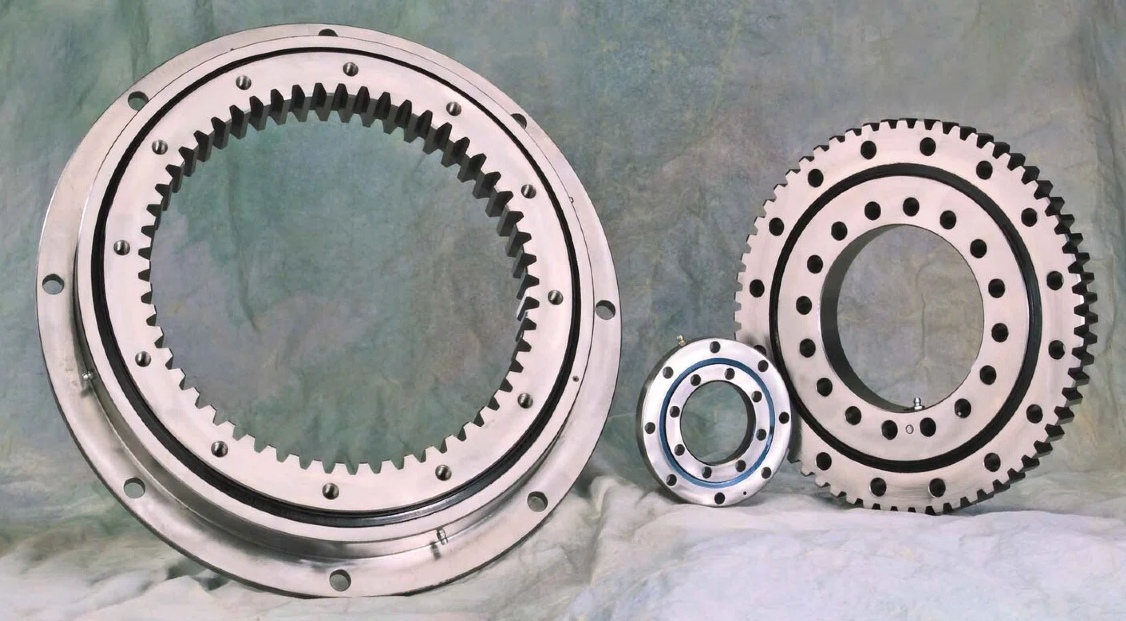
The joint position matters as much as the joint quality. On equipment that swings through a limited arc, such as a boom that works one side, the joint can sit outside the main load zone. On equipment that turns full circles under a moving load, no position avoids it, so the joint must carry its share of the duty.
Alignment, Bolt Preload, Raceway Transitions and Lubrication: The Joint-Level Factors Behind Fatigue Life
Four factors decide whether a joint behaves like part of the ring or like a defect in it. They are linked, so a weakness in one usually shows up in the others.
| Joint factor | What goes wrong | Effect on fatigue life and reliability | What to verify |
|---|---|---|---|
| Segment alignment | A radial or axial step between segments; a gap that opens under load | Rolling elements strike the step on every pass, raising local contact stress | Step and gap measured at the joint, with and without load |
| Bolt preload | Uneven or lost clamping force; relaxation after early cycles | The joint flexes under cyclic load, which fretting and bolt fatigue make worse | Torque or tension method, tightening sequence, re-check after the first duty cycles |
| Raceway transition | Edge burrs, hardness change, or a profile mismatch across the break | Spalling or pitting starts at the edge and spreads along the raceway | Profile and hardness checks across the joint, and a contact pattern test |
| Lubrication continuity | Grease escapes through the gap; seals interrupted at the joint; dry spots on the raceway | Thin or broken lubricant film speeds up wear, and corrosion can enter at the break | Seal design across the joint, grease path, and re-lubrication interval |
Here is how the chain usually runs. Preload relaxes, the faces shift, and a step forms. The step damages the raceway edge, and debris contaminates the grease. Each failure feeds the next one.
That is why we treat the joint as a system, not as a single dimension on a drawing. A perfect flatness figure means little if the bolts lose clamp load in the first few hundred hours. In my 30+ years of design work on heavy equipment, I have found that questions about preload and sealing at the joint tell you more about a design than the bearing's catalog rating does.
What the Evidence Supports and What It Does Not
Public search results on this topic fall into two groups. One leading page cites a 60,000-hour design life with proper maintenance. Other pages explain general bearing types and applications. Few of them describe how segment interfaces affect load transfer and fatigue.
Treat the 60,000-hour figure as a claim, not as a benchmark. It does not state the load spectrum, rotation pattern, joint position or maintenance interval behind it. Search coverage alone does not show an industry trend, and it does not show that segmented rings last longer or shorter than solid ones.
The same caution applies to our own references. The cases we can cite, such as 100 units of SEA21-125-25HR(2) slew drives for slewing platforms in Houston, Texas, and HWE21-94-25HR.1 double worm slew drives for mining excavators in Australia, involve slew drives with continuous bearing rings. They show the heavy cyclic duty that slewing equipment faces. They are not evidence of how long segmented joints last.
Here is how to separate what is observed from what is interpreted:
- Observed: A joint interrupts the raceway and adds bolted interfaces. That is a design fact.
- Plausible interpretation: Those interfaces are where fatigue damage tends to start if preload, alignment or sealing is weak. This matches basic mechanics, but it needs field teardown data to confirm for a given design.
- Alternative explanations: Early failure can also come from a warped mounting surface, overload, poor grease practice or worn seals. A joint can get the blame for damage it did not cause.
- Evidence that would change the view: Inspection records from units with the joint position marked, showing whether damage clusters at the joint or spreads around the ring.
Request Your Custom Slew Drive or Bearing Spec
Tell us your load, speed, and environment — receive a tailored 100–5000 mm slewing drive or slewing bearing proposal with 3D drawings within 24 hours.
Questions to Ask Before Prototype Approval or Retrofit Selection
The checklist below turns the analysis into decisions. Each question shows what it affects.
- Where will the joint sit relative to the main load zone? This decides whether the duty cycle exposes the joint to peak load. It does not help much on full-rotation equipment with a moving load.
- How is the joint clamped, and who verifies preload? This affects bolt fatigue and joint stability. Ask for the tightening method and the re-check plan.
- How are the raceway ends finished and hardened? This affects edge spalling risk. Ask for profile and hardness records across the joint.
- How do the seals and grease path cross the joint? This affects contamination and wear. Ask for the sealing drawing, not just the seal type.
- How stiff is the mounting structure? A flexible frame can open a joint that the bearing alone would hold. This sets how much support surface flatness you must specify.
- Is a solid ring possible? If the ring can pass through the structure, a solid design avoids joint risk entirely. For heavy loads, compare it with three-row roller slewing bearings before committing to segments.
Common Mistakes When Validating a Segmented Design
- Testing only the assembled bearing at rest. Static checks miss joint movement under load. Measure again after running cycles.
- Treating the joint as a cut in a solid ring. It is a bolted interface with its own stiffness, sealing and preload needs.
- Using a service-life number without its conditions. A quoted hour figure means little without load, speed, environment and maintenance assumptions.
- Skipping joint marking in the field. Without a record of joint position, teardown findings cannot be tied to the cause.
- Ignoring the mounting surfaces. Uneven seating can overload one segment, and the joint then looks like the culprit.
One limit applies to all of these. Light, slow or occasional duty may tolerate small joint imperfections for years. The risk rises with heavy cyclic loads, shock, dust and moisture, so match the checks to the real duty.
A Practical Inspection Sequence and What Would Change It
Use this sequence for prototype validation or retrofit acceptance. It needs no special equipment beyond standard measuring tools, and it ties each step to a joint factor above.
- Mark the joint positions on the ring and on the machine frame.
- Check the mounting faces for flatness before the bearing goes on.
- Tighten the bolts in the specified sequence to the design preload.
- Measure step and gap at each joint against the drawing tolerance.
- Run the test cycles, then re-check preload and joint measurements.
- Inspect the raceway contact pattern and the grease condition at the joint.
- Record everything with the joint marks, so later teardowns can be compared.
This is the same discipline we apply in production. Every slew bearing we make passes CMM three-coordinate inspection and dynamic load testing, and our facility is ISO 9001:2015 certified. You can read more about our slew drive quality control process. We cite a failure rate below the 0.5% industry standard and a 2-year extended warranty for our products. These apply to our standard production, not to any specific segmented design.
For a design that does not fit a catalog size, our engineering team can review your drawings and duty cycle. A technical proposal is available within 24 hours. Rapid prototyping takes 3 days, and customized orders start at 5 sets. See our customized slew drive options if the bearing needs to be part of a drive assembly.
Some questions remain open. No public data we can cite shows the real-world gap in service life between segmented and solid rings at equal load. If your teardown results show damage spread evenly around the ring, the joint is not your main risk and you should look at lubrication or mounting first. If damage clusters at the joint, revisit preload, alignment and sealing before changing the bearing size. That evidence should drive your decision, more than any quoted hour rating, when approving a split slew bearing for long-life equipment.
Request Your Custom Slew Drive or Bearing Spec
Tell us your load, speed, and environment — receive a tailored 100–5000 mm slewing drive or slewing bearing proposal with 3D drawings within 24 hours.
 WhatsApp

 +8613903880726