


Enhancing Load Capacity and Transmission Efficiency in Worm Gear Slew Drives
What is Worm Gear Slew Drive
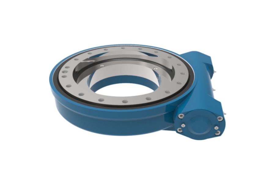
Worm Gear Slew Drive is a specialized rotational actuator combining a compact, high-ratio worm gear reducer integrated directly onto a slewing bearing's inner or outer race. This configuration transforms the input rotation of the worm shaft, typically powered by an electric motor, into a slow, high-torque output rotation of the bearing ring. The fundamental mechanism involves a cylindrical worm screw meshing with and driving a large-diameter worm wheel gear. This unique setup provides exceptional mechanical advantage, self-locking capability under static loads (preventing back-driving), and high precision positioning within a single, robust unit. Essential in applications demanding controlled heavy-duty rotation, such as solar trackers, crane jibs, or radar pedestals, the worm gear interface is the heart of its power transmission and load-bearing function, making its performance optimization paramount.

How to Improve Worm Load Capacity and Transmission Efficiency in Slew Drives
The worm gear interface within a slew drive is susceptible to wear, particularly adhesive wear exacerbated by high loads, speeds, or inadequate lubrication. Premature failure often initiates in specific, high-stress contact zones. Addressing these challenges requires deliberate design interventions during the initial development phase to distribute stress, minimize friction, and ensure effective lubrication film formation:
Optimized Gear Positioning: Precisely adjusting the axial position of the worm relative to the wheel is critical. The goal is to position the primary meshing zone optimally. This encourages the natural formation of an "artificial oil reservoir" on the entry side of the mesh. Simultaneously, it leverages the advantageous conditions on the exit side of the mesh, where the angle between the contact line and the sliding velocity vector is larger. This larger angle promotes better hydrodynamic oil film formation, significantly reducing friction and wear. Typically, the exit side contact should bear approximately 30-40% of the total contact area for balanced load distribution and efficient lubrication.
Elimination of Unfavorable Contact Zones: Conventional worm wheel teeth exhibit a problematic region near the root area, midway along the tooth face. This zone experiences conditions highly detrimental to hydrodynamic oil film formation (low sliding speed, unfavorable pressure angles), often leading to early pitting, scuffing, or adhesive wear. Two primary solutions exist:
Undercut/Relieved Wheel Design ("Gap" or "Pocket" Wheels): Material is intentionally removed from the problematic root zone of the worm wheel tooth flank. This strategic undercutting physically eliminates the high-stress, poorly lubricated contact area, preventing wear initiation in this weak spot.
Precise Meshing Parameter Optimization: Carefully adjusting the worm wheel's tooth count, its precise positioning relative to the worm (center distance, axial offset), and the depth of engagement (backlash control) shifts the primary contact path away from the detrimental root zone towards more favorable areas higher on the tooth flank. This optimization improves load distribution and leverages areas with better lubrication potential.
Creation of Artificial Oil Reservoirs: Deliberately machining recesses ("oil pockets" or reservoirs) into the worm wheel tooth flanks significantly enhances lubrication retention and hydrodynamic film formation within the mesh:
Oversized Hob Method: The worm wheel is cut using a hob (cutting tool) with a diameter larger than the mating worm. As this larger-diameter hob generates the wheel tooth profile, it inherently creates a recessed area along the pitch line – an artificial oil reservoir perfectly aligned with the worm's path. This reservoir consistently supplies lubricant directly into the critical contact zone.
Hob Offset Method: Using a standard-sized hob, the tool is deliberately shifted axially relative to the worm wheel blank during the cutting process. By subsequently adjusting the hob's tilt angle (swivel angle) to maintain the correct tooth helix angle, this offset machining technique creates the desired recessed oil pocket on the wheel flank.
Implementing these strategies – precise positioning, eliminating weak contact zones, and ensuring ample lubrication reservoirs – directly combats the primary causes of adhesive wear. The result is a substantial increase in the worm drive's ability to handle higher loads (load capacity) and a significant reduction in friction losses, translating directly to higher mechanical efficiency and longer operational life.
Key Features of Worm Gear Slew Drives
Worm Gear Slew Drives offer a compelling set of characteristics derived from their core worm gear mechanism:
High Torque Density & Reduction Ratios: Achieves very high output torque relative to its size and input power, often with single-stage reduction ratios exceeding 100:1, sometimes reaching 300:1 or higher.
Inherent Self-Locking: The friction angle within the worm mesh typically prevents the output load from back-driving the worm screw when power is removed, providing crucial safety and holding capability without additional brakes (though dynamic braking may still be required for controlled stopping).
Compact & Integrated Design: Combines the reducer and the slewing bearing into a single, space-saving unit, simplifying mounting and reducing the overall system footprint.
Smooth & Quiet Operation: The sliding contact of the worm mesh, when properly lubricated and manufactured, results in relatively quiet and low-vibration motion, beneficial for precision applications.
High Axial & Moment Load Capacity: The integrated slewing bearing is inherently designed to handle substantial combined radial, axial, and moment loads directly at the point of rotation.
High Positioning Accuracy & Repeatability: Minimal backlash variants offer excellent control over rotational positioning.
Primary Applications of Worm Gear Slew Drives
The unique advantages of Worm Gear Slew Drives make them indispensable across numerous demanding sectors:
Solar Energy: Universally employed in photovoltaic (PV) solar trackers (single-axis and dual-axis) to precisely orient solar panels towards the sun throughout the day, maximizing energy capture.
Material Handling & Cranes: Powering the slewing motion of crane jibs, knuckle booms, man-lifts, aerial work platforms, and robust industrial positioners.
Wind Energy: Used for yaw control (nacelle positioning) and pitch control (blade angle adjustment) in wind turbines.
Construction Equipment: Found in excavator attachments, concrete pumpers, drilling rigs, and compact crane attachments requiring precise rotational positioning under load.
Industrial Automation & Machinery: Used in welding positioners, indexing tables, robotic arms, large valve actuators, packaging machinery, and radar/satellite dish positioning systems.
Medical & Defense: Applied in specialized equipment requiring high torque, precision, and compactness, such as medical imaging devices or turret systems.
Factors Influencing Worm Gear Slew Drive Pricing
The cost of a Worm Gear Slew Drive is determined by a complex interplay of design, manufacturing, and market factors:
Size & Load Capacity: Larger drives engineered to handle higher axial/radial loads, overturning moments, and output torque command significantly higher prices due to increased material volume, larger bearings, and heavier machining requirements.
Precision & Performance Level: Drives requiring ultra-low backlash (< 5 arc-min), extremely high positional repeatability, or exceptionally high efficiency demand tighter manufacturing tolerances, specialized gear grinding, superior bearing selection, and rigorous quality control, increasing cost.
Worm/Wheel Material & Heat Treatment: Using high-strength alloy steels (e.g., 42CrMo, 20MnCr5) instead of standard carbon steel, coupled with advanced case hardening processes (carburizing, nitriding, induction hardening) and precision grinding of tooth flanks, dramatically increases durability and performance but also cost.
Bearing Type & Quality: The integrated slewing bearing's type (ball, cross roller), size, precision grade, sealing effectiveness, and manufacturer reputation are major cost components.
Sealing & IP Rating: Achieving high Ingress Protection (IP65, IP66, IP67) ratings for harsh environments (dust, water, chemicals) requires complex multi-lip seals, specialized lubricants, and meticulous housing design, adding cost.
Gear Manufacturing Complexity: Implementing optimized designs (e.g., undercut wheels, artificial oil pockets via oversized/offset hobbing) requires specialized tooling, setup, and machining expertise compared to standard gear cutting.
Lubrication System: Integrated automatic lubrication systems or requirements for special high-performance greases add to the overall cost.
Customization & Quantity: Highly customized designs (unique mounting flanges, special shaft configurations, specific coatings) incur significant engineering and setup costs. Conversely, higher production volumes typically reduce unit cost through economies of scale.
Brand Reputation & Quality Certification: Drives from manufacturers with established reputations for reliability and holding stringent quality certifications (ISO 9001, etc.) often command premium pricing.
Geographic Market & Raw Material Costs: Fluctuations in global steel prices, tariffs, and regional manufacturing costs directly impact the final price.
Reliable Worm Gear Slew Drive Supplier
LYRADRIVE stands as a prominent designer and manufacturer specializing in high-performance Worm Gear Slew Drives engineered for demanding applications globally. We focus on delivering robust solutions that prioritize durability, efficiency, and precise motion control. Leveraging expertise in gear design and advanced manufacturing processes, LYRADRIVE products incorporate critical optimizations such as precisely positioned meshing, strategic tooth profile modifications, and effective lubrication features to maximize worm load capacity and transmission efficiency, directly addressing the core challenges discussed. Our comprehensive range caters to diverse industries, including rigorous solar tracking, heavy-duty material handling, and sophisticated automation systems. LYRADRIVE is committed to providing technical support, customization options, and reliable supply chains to meet specific customer requirements. Explore our capabilities at https://www.lyradrive.com/.
.