


Spur Gear Slew Drive Tooth Machining Requirements
What is Spur Gear Slew Drive
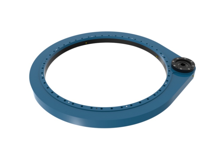
Spur Gear Slew Drive is a fully integrated mechanical actuator system designed to provide controlled, high-torque rotational movement about a single axis. It represents a complete fusion of a robust drive motor (typically hydraulic or electric), a high-ratio speed reducer such as a worm gearbox, and a large-diameter slewing ring bearing with a spur (straight-cut) gear machined directly onto either its inner or outer ring. This integrated design distinguishes it from systems where these components are sourced and assembled separately. The primary function of a slew drive is to efficiently transform the high-speed, low-torque output of its input motor into a slow-speed, high-torque rotational output, enabling it to manage immense loads with precise control. The term "spur gear" specifically refers to the geometry of the gear teeth on the slewing ring; these teeth are straight and aligned parallel to the axis of rotation, which differentiates it from other drives using helical or bevel gears. This configuration is prized for its manufacturing simplicity, ease of installation and maintenance, and its ability to deliver high power transmission efficiency in a compact and robust package, making it a cornerstone component in heavy machinery where reliability under extreme stress is paramount.

Tooth Machining Requirements for Spur Gear Slew Drive
The machining of the spur gear teeth on a slew drive's slewing ring is a precision engineering process that directly dictates the performance, efficiency, noise level, and service life of the entire drive system. The requirements for this process are stringent and multi-faceted, encompassing the selection of manufacturing equipment, the achievement of precise geometric tolerances, and the implementation of appropriate heat treatment protocols to achieve the necessary surface hardness and core toughness.
The choice of machining equipment is fundamental and is primarily determined by the gear's location and the required production efficiency. External gears, which are machined on the outer circumference of the ring, are typically produced using high-precision gear hobbing machines. A hobbing cutter rotates and traverses along the workpiece, gradually generating the tooth profile with high efficiency and accuracy. For internal gears, where the teeth are cut into the inner bore of the ring, gear shaping machines or internal gear hobbers are employed. A gear shaper uses a reciprocating cutter that mimics the meshing action of a gear to generate the teeth. A critical advancement in manufacturing technology is the adoption of multi-axis milling machines equipped with advanced carbide cutting tools. These CNC-controlled machines offer exceptional flexibility and can often produce both internal and external gears with high accuracy and superior surface finish, reducing cycle times and allowing for more complex tooth forms to be machined. The machining process is never a single-step operation for quality gears. It is a multi-stage sequence: roughing first removes the bulk of the material, followed by semi-finishing to bring the gear close to its final dimensions. The final and most critical stage is finishing, which achieves the exact tooth profile, lead, and pitch required. For applications demanding the utmost precision and quietest operation, such as in medical imaging or high-precision automation, a final gear grinding operation is performed after heat treatment. Grinding eliminates any minor distortions from hardening and achieves micron-level accuracy in tooth geometry, ensuring perfectly smooth and efficient meshing with the drive pinion.
Beyond the machining process itself, the geometric accuracy of the teeth is governed by a strict set of tolerance requirements. Tooth profile accuracy ensures that the involute curve of each tooth is perfect, preventing concentrated stress points and ensuring smooth power transfer. Pitch accuracy guarantees that the distance between every tooth is consistent around the entire circumference, preventing velocity fluctuations and uneven load sharing. Lead accuracy controls the alignment of the tooth face relative to the axis, preventing edge loading and ensuring the contact pattern is evenly distributed across the full face width of the tooth. Runout tolerance ensures the gear teeth are concentric with the bearing's axis of rotation, which is critical for minimizing vibration and achieving smooth operation. These tolerances are rigorously checked using coordinate measuring machines (CMMs) and specialized gear inspection equipment like gear analyzers.
The final and equally critical requirement is heat treatment. The gear teeth are subject to constant wear and high contact stresses. To withstand this, their surface hardness must be significantly increased. The most common and effective method is induction hardening, which uses an electromagnetic field to rapidly heat only the surface layer of the tooth to austenitizing temperature before it is immediately quenched, transforming it into an extremely hard martensitic structure. This process can be applied in two ways: full-circle induction hardening passes the entire ring through an inductor, while single-tooth induction hardening treats each tooth individually, offering superior control and minimizing geometric distortion. The resulting surface hardness must typically be within a range of HRC 50-60, and the hardened case depth must be controlled to a specified depth (e.g., 2-5mm) to provide a strong support for the hard surface layer. Crucially, the core of the tooth and the underlying material of the slewing ring must remain tough and ductile to absorb impact loads without fracturing, a property achieved through a prior normalizing or quenching and tempering process. This combination of a hard wear-resistant surface and a tough, shock-absorbing core is what gives the gear teeth their exceptional durability and resistance to pitting, spalling, and tooth breakage.
Characteristics of Spur Gear Slew Drive
Spur Gear Slew Drives are defined by a distinct set of engineering characteristics that make them indispensable for high-torque, low-speed rotational applications. Their most defining feature is the exceptionally high torque output delivered in a compact and integrated package. By combining a high-ratio worm gear reducer with a large-diameter slewing ring, they achieve massive mechanical advantage, allowing relatively small input motors to control and move immensely heavy loads with precision. This integrated design eliminates the need for custom-designed mounting solutions for separate components, simplifying machine design, saving space, and reducing the overall number of parts in the system, which enhances reliability.
A key operational characteristic is their inherent self-locking capability when a worm gear reducer is employed. The design of the worm and worm wheel creates a high friction angle that prevents back-driving. This means that when the input drive stops, the load is immediately and reliably held in position without the need for an external braking system. This is a critical safety feature in applications like crane booms, solar trackers, or lifting platforms where maintaining a stationary position under load is absolutely essential. Furthermore, spur gear slew drives are renowned for their robustness and durability. They are constructed from high-strength, hardened steel alloys (e.g., 42CrMo4 for rings) and are designed to operate reliably under severe conditions, including exposure to heavy shock loads, vibrations, and harsh environmental elements, thanks to their protective sealing systems.
The use of a spur gear offers specific advantages. Compared to helical gears, spur gears are simpler to manufacture, inspect, and maintain. Their straightforward geometry allows for easier alignment during installation and meshing with the pinion. While they can be slightly noisier than helical gears at very high speeds, this is less of a concern in the slow-speed, high-torque applications where slew drives excel. Finally, these drives offer significant design flexibility. They can be configured with the gear on the inner or outer ring, sourced with different sealing and lubrication options for various environments, and customized with a range of input motors (electric, hydraulic) and gear reduction ratios to meet the exact torque and speed requirements of a specific application.
Applications of Spur Gear Slew Drive
The application of spur gear slew drives is extensive across industries that require robust, controlled, and powerful rotational movement. In the construction and heavy machinery sector, they are the fundamental actuation system in the boom rotation of mobile cranes, enabling precise positioning of heavy loads. They are also critical in concrete pump trucks for controlling the placement boom and in excavators for providing rotation in compact swing drives.
The renewable energy industry is a major and growing application field. Slew drives are the core component in solar tracking systems for both photovoltaic (PV) panels and concentrated solar power (CSP) systems. They provide the precise, powerful rotation needed to accurately angle solar arrays throughout the day, significantly increasing energy capture. Similarly, they are used in the yaw and pitch control systems of smaller wind turbines, adjusting the nacelle and blades to optimize performance.
In industrial automation and material handling, these drives are essential. They operate the rotating bases of robotic welding and assembly arms, provide motion for indexing tables on heavy-duty machining centers, and are found in rotary conveyors and palletizers. The mining and agricultural industries rely on them for robust performance in stackers, reclaimers, and heavy-duty tractors. Furthermore, their high precision and holding power make them suitable for specialized applications such as radar and satellite antenna positioning, medical imaging equipment like CT scanners, and even in deck cranes and winches on marine vessels.
Factors Influencing the Price of Spur Gear Slew Drive
The price of a spur gear slew drive is determined by a confluence of technical specifications, material choices, and commercial factors. The single largest cost driver is often the size and material of the core slewing ring. Larger diameters require more raw material and more complex machining processes. The grade of steel (e.g., standard 50Mn or high-strength 42CrMo4) and the extent of heat treatment (induction hardening) applied to the raceways and gear teeth significantly impact cost, as does the choice of rolling element (ball vs. more expensive crossed roller).
The level of customization and complexity is another major determinant. A standard, catalogued unit is more economical than a fully custom-designed drive. Customizations such as special gear specifications (module, precision grade), unique mounting hole patterns, specific seal materials for extreme temperatures, special surface coatings (e.g., anticorrosion treatments), and integrated sensors drastically increase manufacturing overhead. The specifications of the included components, namely the type and power of the input motor (standard electric motor vs. a customized hydraulic motor) and the design of the gear reducer, also form a significant portion of the total cost.
Performance requirements directly influence price. Drives manufactured to standard industrial tolerances are cost-effective. Those produced to ultra-precise, micron-level tolerances for applications like medical imaging or aerospace, which require 100% non-destructive testing (NDT), full material traceability, and extended performance validation, command a premium. Finally, order quantity and external factors play a role. Large volume orders benefit from economies of scale, reducing the unit cost. Global fluctuations in steel prices, international shipping costs, and import/export tariffs can also cause price variations.
Supplier of Spur Gear Slew Drive
For engineers seeking a reliable source for high-performance spur gear slew drives, LYRADRIVE stands as a manufacturer with deep expertise in the engineering and production of these integrated systems. The company provides comprehensive technical support, guiding customers through selection, installation, and maintenance best practices to ensure optimal performance and longevity. This support is backed by a rigorous quality management system governing every production stage, from material forging and precision gear hobbing to heat treatment, final assembly, and testing. By offering advanced manufacturing capabilities and a commitment to delivering robust and reliable drive solutions, LYRADRIVE has established itself as a trusted partner for a global clientele across diverse industries such as solar tracking, construction, and industrial automation.