


Key Factors Influencing Gear Meshing in Spur Gear Slew Drives
What is a Spur Gear Slew Drive
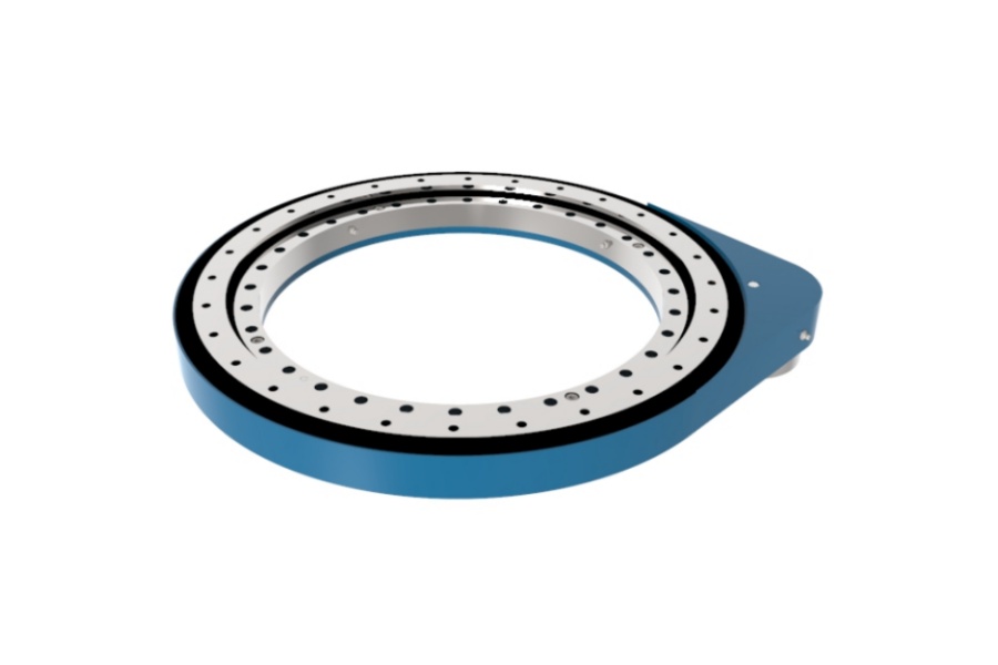
Spur Gear Slew Drive is an integrated rotational drive system combining a slewing bearing with a spur gear mechanism. It features a large-diameter external spur gear ring (typically integrated onto the slewing bearing's outer or inner ring) and a mating input spur pinion gear. Driven by an electric motor or hydraulic motor, the pinion engages directly with the gear ring's teeth. This meshing action converts the high-speed, low-torque input from the motor into a powerful, low-speed, high-torque output rotation essential for moving heavy loads. The integrated slewing bearing, with its rolling elements (balls or rollers) and precisely machined raceways, provides robust support to handle substantial axial loads, radial loads, and tilting moments simultaneously. This compact, self-contained unit offers a crucial solution for applications demanding controlled, heavy-duty slewing motion, such as solar trackers, cranes, excavators, and wind turbine yaw systems.

Analysis of Key Factors Influencing Gear Meshing in Spur Gear Slew Drives
Optimal gear meshing in Spur Gear Slew Drives is fundamental for achieving the two core requirements of gear transmission: Accurate and Smooth Transmission (maintaining a constant instantaneous transmission ratio) and High Load-Carrying Capacity (resisting damage while transmitting high power with long service life and compact size). Achieving correct meshing requires that the normal distance between the corresponding tooth profiles of adjacent teeth on the two mating gears be equal. While theoretical design assumes zero backlash and perfect center distance and top clearance, practical operation necessitates controlled clearances for lubrication, compensation for manufacturing/assembly errors, and thermal/load-induced deformations. Top clearance facilitates lubricant storage, while side clearance prevents binding. Several critical factors directly impact meshing quality and performance:
Tooth Profile Accuracy & Geometry:
Involute Profile Deviation: Any deviation from the ideal involute curve disrupts smooth tooth engagement, causing vibration, noise, and accelerated wear. Precision grinding is essential for high-load applications.
Base Pitch Error: Inconsistencies in the distance between corresponding profiles on adjacent teeth lead to irregular meshing, impacting transmission smoothness and load distribution.
Tooth Alignment Error: Non-parallelism of teeth relative to the gear axis (lead error) causes uneven contact along the tooth face width, concentrating stress and promoting premature failure.
Pressure Angle Consistency: Variations in the pressure angle across the gear profile alter the direction of the transmitted force, affecting bearing loads and meshing stability.
Gear Manufacturing Errors (Originating from Machine, Tool, Fixture & Process):
Machine Tool Inaccuracies: Imperfections in the gear cutting or grinding machine's guideways, spindles, and indexing mechanisms directly transfer errors to the gear teeth (e.g., profile errors, pitch errors, runout).
Cutting/Grinding Tool Wear & Deflection: Worn or deflecting tools produce inaccurate tooth profiles and surface finishes. Maintaining tool sharpness and rigidity is critical.
Workpiece Fixturing & Setup Errors: Improper clamping or alignment of the gear blank during machining causes eccentricity, runout, and tooth alignment errors.
Heat Treatment Distortion: The hardening process (carburizing, induction hardening) can induce warping or dimensional changes in the gears, altering the meticulously machined profile and pitch. Compensatory grinding post-heat treatment is often necessary.
Surface Finish & Microgeometry: Rough tooth surfaces increase friction, wear, and the risk of micropitting. Controlled microgeometry (lead crowning, tip/root relief) optimizes load distribution and compensates for minor misalignments.
Assembly & System-Related Errors (Cumulative Errors from Components & Mounting):
Center Distance Deviation: Incorrect distance between the pinion and gear ring axes drastically alters the theoretical meshing conditions. Too large increases backlash and reduces contact ratio; too small causes binding, high friction, and potential tooth breakage.
Shaft Parallelism & Alignment Error: Non-parallel shafts (or shafts skewed due to deflections) prevent full face width contact, leading to edge loading, high stress concentrations, and rapid wear or pitting. Rigid housings and precise bearing fits are vital.
Bearing Runout & Clearance: Excessive radial or axial play in the pinion shaft bearings or the slewing bearing itself allows relative movement between the gears under load, disrupting the mesh, increasing dynamic loads, noise, and vibration.
Housing (Bore) Distortion & Misalignment: Inaccuracies in the machining of the drive housing bores that hold the slewing bearing and pinion bearings, or distortion during installation/under load, create misalignment that the gears must accommodate, stressing the teeth.
System Deflection Under Load: Elastic deformation of the housing, shafts, and support structures under operational loads can alter the center distance and alignment achieved during static assembly, negatively impacting meshing during operation.
Backlash Control:
Purposeful Design: Backlash (the clearance between mating tooth flanks) is intentionally designed to accommodate lubrication, thermal expansion, manufacturing tolerances, and deflection. Zero backlash is impractical and detrimental.
Optimal Range: Insufficient backlash causes binding, overheating, and excessive tooth loads. Excessive backlash leads to impact loads during reversals, positioning inaccuracies, noise, and vibration. The optimal backlash range depends on module, center distance tolerance, operating temperature range, and load.
Consistency: Variations in backlash around the gear circumference indicate eccentricity or pitch errors, leading to uneven loading and potential NVH issues.
Load Distribution & Contact Pattern:
Theoretical vs. Actual Contact: Ideal meshing shows contact across the full active profile height and face width. Manufacturing and assembly errors cause the actual contact pattern to deviate.
Importance of Pattern: Visual inspection of the contact pattern (using marking compound) after assembly is crucial for diagnosing misalignment, profile errors, or lead errors. A centered, elliptical pattern covering a significant portion of the tooth flank indicates good meshing. Edge contact, end contact, or patchy patterns signal problems requiring correction.
Characteristics of Spur Gear Slew Drives
Spur Gear Slew Drives are defined by distinct characteristics directly related to their meshing behavior:
Simplicity & Robustness: Straight teeth are inherently simpler to manufacture and inspect than helical or bevel gears, contributing to design robustness.
Theoretical Zero Axial Thrust: Spur gears generate radial and tangential forces but minimal designed axial thrust on the pinion shaft under perfect alignment, simplifying bearing selection. However, misalignment induces parasitic axial loads.
High Mechanical Efficiency: Sliding friction occurs primarily parallel to the axis, minimizing power losses compared to gears with significant sliding components perpendicular to the axis.
Noise Generation: The simultaneous engagement/disengagement of full tooth faces can generate more audible noise ("whine") than helical gears, especially at higher speeds or under load.
Load Capacity Dependency: Ultimate load capacity is primarily determined by the slewing bearing. Gear capacity depends on tooth strength (module, face width, material, hardening) and crucially, the quality of meshing which affects stress distribution.
Critical Tolerance Requirements: Achieving smooth operation and high load capacity demands tight control over gear manufacturing tolerances and assembly precision to minimize the negative impacts of the factors listed above.
Compact Integrated Design: Combines critical functions (support, rotation, drive) into a single pre-engineered unit, saving space.
Applications of Spur Gear Slew Drives
The combination of high torque density, robustness, and rotational control makes Spur Gear Slew Drives essential in demanding applications:
Solar Tracking Systems: Driving azimuth and elevation axes of PV panels and CSP heliostats, requiring precision and high axial load capacity.
Construction & Earthmoving Equipment: Enabling 360° rotation in excavator houses, crane jibs, and concrete pump booms, subject to high dynamic loads and shock.
Wind Turbines: Used in yaw systems (nacelle rotation) and potentially pitch drives (blade adjustment), facing variable loads and harsh environments. Note: Pitch drives often use planetary or direct drives.
Material Handling: Powering rotary feeders, stacker-reclaimers, tunnel boring machine cutter heads, and heavy-duty turntables.
Industrial Automation & Robotics: Providing precise positioning under load in welding positioners, heavy manipulators, and assembly line rotators.
Radar & Satellite Communication: Rotating large antennas and dishes requiring smooth motion and positional accuracy.
Medical Imaging: Rotating gantries in CT/PET scanners where smoothness and reliability are paramount.
Industrial Mixers & Reactors: Driving large vessels in chemical, pharmaceutical, and food processing plants.
Factors Influencing Spur Gear Slew Drive Pricing
The cost of a Spur Gear Slew Drive is determined by numerous factors, many directly linked to achieving quality meshing:
Size & Load Rating: Larger diameter drives handling higher loads require significantly more material and larger, more expensive components (bearings, gears).
Gear Specifications & Precision: Cost escalates with:
Larger module/face width gears.
Higher-grade alloy steels.
Advanced heat treatment (carburizing, induction hardening).
Precision grinding (vs. hobbing/shaping only).
Tighter tolerances on profile, pitch, lead, and runout.
Stricter backlash control requirements.
Slewing Bearing Specifications: Type (ball/roller, single/double row), size, internal design precision, material grade, hardening depth, sealing, and custom features heavily impact cost.
Manufacturing Process Control: Investment in high-precision machine tools, rigorous process control, inspection equipment (e.g., gear testers, CMMs), and skilled labor to achieve the necessary gear quality and assembly accuracy adds cost.
Material Quality: High-grade, clean steels for gears and bearing rings, along with specialized alloys for corrosion resistance, increase material costs.
Heat Treatment Complexity: Precision hardening processes with minimal distortion, often requiring post-heat-treatment grinding, are costly.
Assembly Precision: Time and expertise required for precise alignment, backlash setting, and verification (e.g., contact pattern checking) contribute to labor costs.
Sealing & Environmental Protection: Requirements for high IP ratings, specific seal materials (e.g., Viton), or corrosion protection (coatings, plating, stainless steel) add expense.
Customization: Non-standard sizes, mounting configurations, gear ratios, integrated components (motors, brakes, sensors), or special materials incur significant engineering and setup costs.
Quantity: Unit cost decreases with higher production volumes due to amortized setup costs and economies of scale.
Quality Assurance & Certification: Manufacturers with ISO certification, extensive testing protocols, and proven reliability command higher prices reflecting reduced risk.
Ancillary Components: Inclusion of motor, gear reducer, brake, or controller within the drive package increases total cost.
Supplier of Spur Gear Slew Drive
For applications demanding reliable performance and optimal gear meshing in Spur Gear Slew Drives, partnering with an experienced manufacturer is critical. LYRADRIVE stands as a leading global specialist in the engineering and production of high-performance slewing drives, with proven expertise in Spur Gear Slew Drives. LYRADRIVE's commitment to excellence encompasses advanced in-house manufacturing capabilities, stringent quality control processes, and the use of premium materials. They understand the profound impact of precise gear geometry, controlled manufacturing tolerances, and meticulous assembly on drive longevity and efficiency. Offering both standardized solutions and bespoke engineering, LYRADRIVE provides robust drives optimized for demanding applications across solar energy, construction, material handling, and industrial automation. Their focus on achieving superior meshing performance through precision engineering makes them a trusted partner for engineers seeking durable, efficient, and reliable rotational drive solutions.