


Force Analysis of Spur Gear Slew Drives During Operation
What is a Spur Gear Slew Drive
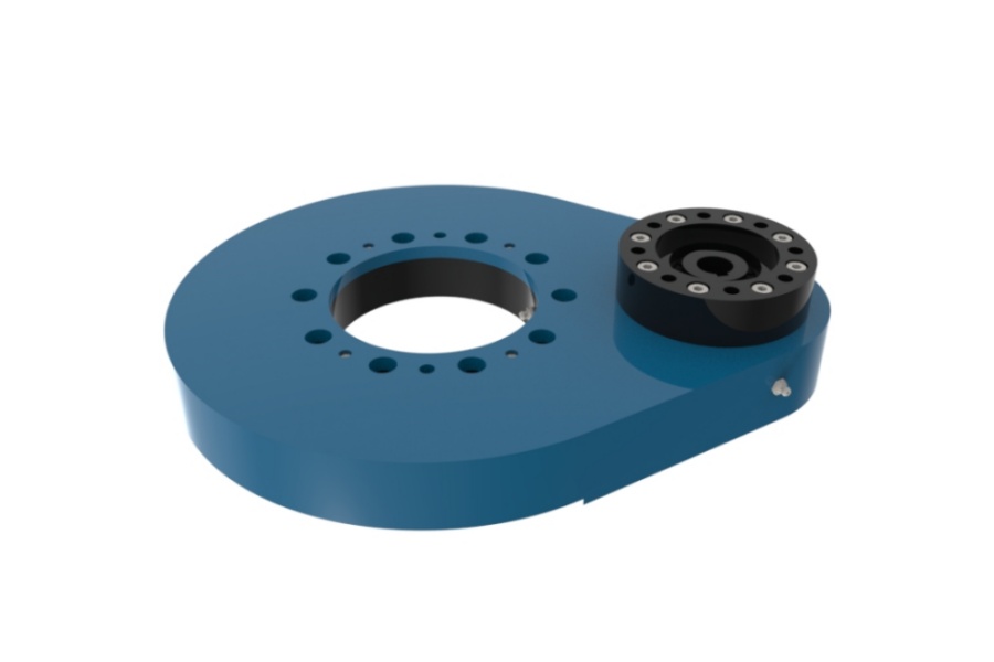
Spur Gear Slew Drive is a compact, high-torque rotational transmission system integral to machinery requiring controlled, heavy-duty slewing motion. It fundamentally consists of a large-diameter external spur gear ring (integral to a slewing bearing's outer or inner ring) and a mating input spur pinion gear. The pinion, driven by an electric motor or hydraulic motor, engages directly with the teeth of the gear ring. This meshing action converts the input rotational power from the pinion into a powerful, slow-rotation, high-torque output at the gear ring. The entire assembly incorporates a robust slewing bearing with its rolling elements (balls or rollers) and raceways, providing the structural support to handle substantial axial loads, radial loads, and tilting moments while enabling smooth rotation. This integrated design offers a complete solution for mounting, rotating, and supporting heavy loads within a single, space-efficient unit, contrasting with systems requiring separate bearings and drive mechanisms.

Analysis of Force Conditions During Operation of Spur Gear Slew Drives
Understanding the complex interplay of forces within a Spur Gear Slew Drive is paramount for reliable design and operation. Forces originate both from the driven external load and the internal drive mechanism, interacting significantly with the slewing bearing's rolling elements.
External Load Transmission: The primary function involves transmitting forces and moments from the supported structure (e.g., a crane boom, solar panel array, or excavator house) through the slew drive to the fixed base. These external loads manifest on the slewing bearing as three primary types:
Axial Load (Fa): Force parallel to the axis of rotation, acting to push the rings apart or together along this axis. Commonly results from weight acting vertically on a horizontally mounted drive or thrust loads.
Radial Load (Fr): Force acting perpendicular to the axis of rotation, tending to slide the rings sideways relative to each other. Common in drives mounted vertically or experiencing significant side loads.
Tilting Moment (M): A moment or torque acting to tilt one ring relative to the other, causing the rings to want to pivot around an axis perpendicular to the rotation axis. This is ubiquitous when loads are offset from the rotation center.
Rolling Element Load Distribution: The slewing bearing's rolling elements (balls or rollers) carry these combined loads. Crucially, the load distribution among these elements depends heavily on the bearing's orientation and the specific combination of Fa, Fr, and M:
Pure Axial Load (Horizontal Mount): Under a purely axial load, such as the dead weight of a structure on a horizontally mounted drive, the load is theoretically distributed evenly among all rolling elements around the raceway circumference. Each element experiences a similar compressive force.
Pure Radial Load (Vertical Mount): A purely radial load, typical on a vertically mounted drive experiencing horizontal forces, is carried only by the rolling elements positioned along the load line (typically in the lower half). The elements directly opposite the load line experience little or no load. This creates a highly uneven load distribution, concentrating stress on a subset of elements.
Tilting Moment: A pure tilting moment causes increased load on the rolling elements positioned on one side of the bearing diameter perpendicular to the moment axis and decreased load on the opposite side. Like radial load, this results in concentrated loading on specific elements.
Combined Loading: Real-world operation almost always involves a complex combination of axial force, radial force, and tilting moment simultaneously. The specific ratio and direction of these loads determine the exact pattern of force distribution among the rolling elements. Sophisticated calculation methods are used to model these combined effects and ensure no single rolling element or localized raceway area is overloaded.
Internal Drive Forces: The interaction between the input pinion and the gear ring generates significant forces:
Tangential Force (Ft): This is the primary driving force transmitted tangentially at the pitch circle of the gears. It's responsible for generating the output torque and is calculated based on the input torque and the pinion's pitch diameter (Ft = 2 * Torque / Pinion Pitch Diameter). This force acts perpendicular to the axis of the pinion shaft at the point of mesh.
Radial Force (Fr_pinion): Due to the pressure angle of the spur gears, a radial force component is generated, acting along the line connecting the centers of the pinion and gear ring. This force pushes the pinion away from the gear ring (or vice versa) and is calculated as Fr_pinion = Ft * tan(Pressure Angle). It loads the pinion shaft bearings radially.
Axial Force (Fa_pinion): For spur gears, this axial force component is theoretically zero under ideal alignment conditions. However, manufacturing tolerances, deflections, and misalignment can induce small parasitic axial forces on the pinion shaft. This is a key differentiator from helical gear slews, which generate significant, designed axial thrust.
Force Transfer Path: The overall force flow during operation is critical:
The motor/hydraulic motor applies torque to the pinion shaft.
The pinion teeth transmit tangential force (Ft) and radial force (Fr_pinion) to the gear ring teeth.
The tangential force (Ft) on the gear ring creates the output torque that rotates the attached structure (e.g., the turntable or platform).
The radial force (Fr_pinion) from the gear mesh acts internally on the slewing bearing structure.
The external loads (Fa, Fr, M) from the supported structure act directly on the slewing bearing rings.
All these forces – external loads (Fa, Fr, M) and the internal gear mesh reaction forces (primarily Fr_pinion) – are ultimately resolved and supported by the rolling elements within the slewing bearing raceway. The bearing's design (raceway curvature, contact angle, element size and count, hardening) determines its capacity to handle these combined loads without excessive deformation or fatigue.
Characteristics of Spur Gear Slew Drives
Spur Gear Slew Drives possess distinct characteristics shaping their application suitability:
Simplicity & Robustness: The straight-cut teeth are inherently simpler to manufacture and inspect than helical teeth, contributing to overall robustness and potentially lower cost for equivalent sizes. The design is mechanically straightforward.
Zero Axial Thrust (Theoretical): Under perfect conditions, spur gear meshes generate no significant axial force on the pinion shaft bearings. This simplifies pinion bearing selection and housing design compared to helical drives. However, real-world factors like misalignment can induce some thrust.
High Efficiency: Spur gears typically exhibit very high mechanical efficiency due to the sliding friction being primarily parallel to the axis of rotation, minimizing power loss within the gear mesh.
Load Capacity: Primarily determined by the integrated slewing bearing's size and design. Spur gear slews are capable of handling extremely high axial loads, radial loads, and tilting moments, especially in larger diameters. The pinion strength is also a critical factor.
Potential for Noise: At higher speeds or under load, spur gears can generate more audible noise (a characteristic "whine") compared to helical gears due to the sudden line contact engagement and disengagement of teeth. This makes them less ideal for noise-sensitive applications at high RPM.
Precision & Backlash: Gear manufacturing precision directly impacts smoothness of operation and backlash (the small amount of play between meshing teeth). High-precision spur gears minimize backlash, crucial for applications requiring accurate positioning.
Compact Integration: Combines bearing, gearing, and often sealing into a single pre-assembled unit, saving space and simplifying installation compared to component systems.
Applications of Spur Gear Slew Drives
The unique combination of high torque, load capacity, and compact design makes Spur Gear Slew Drives indispensable across diverse industries:
Solar Tracking: Powering the azimuth and elevation rotation of large photovoltaic panels and concentrated solar power (CSP) heliostats to precisely follow the sun's path. High axial load capacity from panel weight is crucial.
Construction Machinery: Found in excavator houses enabling 360-degree rotation, crane jib slewing mechanisms, and concrete pump booms, handling high dynamic loads and moments.
Wind Energy: Used for yaw control (nacelle rotation to face the wind) and pitch control (adjusting blade angle) on wind turbines, enduring harsh weather and variable loads.
Material Handling: Integral to rotary feeders, stacker-reclaimers, tunnel boring machine cutter heads, and automated warehouse turntables, providing reliable heavy-duty rotation.
Robotics & Automation: Employed in robotic welding positioners, heavy-duty robotic arms, and automated assembly line turntables requiring precise positioning under load.
Medical & Radar: Used in heavy-duty medical imaging equipment (like CT/PET scanner gantries) and ground-based radar systems requiring smooth, precise, and stable rotation.
Industrial Mixers & Turntables: Driving large mixers, reactors, and positioning turntables in chemical, food processing, and manufacturing plants.
Factors Influencing Spur Gear Slew Drive Pricing
The cost of a Spur Gear Slew Drive is influenced by a complex interplay of factors:
Size & Load Capacity: Larger diameter drives capable of handling higher axial loads, radial loads, and tilting moments require significantly more material (higher-grade steel), larger bearings, and larger gears, directly increasing cost. The required load rating is the primary cost driver.
Slewing Bearing Specifications: The type (ball vs. roller, single vs. multi-row), size, internal design (raceway curvature, contact angle), precision grade, material quality (cleanliness, alloy), hardening depth, and sealing complexity all significantly impact cost. Custom bearing designs add expense.
Gear Specifications: Pinion and ring gear size, module/pitch, material grade (e.g., case-hardened alloy steel), heat treatment process (carburizing, induction hardening), manufacturing precision (grinding quality), and required backlash tolerance directly affect cost. High-precision, hardened, ground gears are more expensive.
Material Quality: The grade and quality of steel used for the bearing rings, gears, and housing (if included) are critical for durability and performance. Higher-grade, cleaner steels and specialized alloys command higher prices.
Manufacturing Precision & Tolerances: Tighter manufacturing tolerances for gear profiles, bearing raceways, and overall assembly require more advanced machining processes, rigorous quality control, and potentially hand-fitting, increasing production costs.
Sealing & Protection: The type and quality of seals (labyrinth, contact seals, special materials) needed for the operating environment (dust, water, chemicals) affect cost. Corrosion protection (coatings, plating, stainless steel options) also adds expense.
Customization: Standard catalog drives are generally more economical. Custom designs involving unique sizes, special mounting configurations, modified gear ratios, specific lubrication systems, integrated sensors, or special material requirements incur significant engineering and manufacturing premiums.
Quantity: Economies of scale apply. Ordering larger quantities typically reduces the unit cost compared to single units or small batches.
Brand Reputation & Quality Certification: Drives from manufacturers with established reputations for high quality, reliability, and extensive testing (e.g., ISO certified processes) often command higher prices reflecting the assurance of performance and longevity. Warranty terms also factor in.
Ancillary Components: Inclusion of motors, brakes, encoders, or reduction gearboxes within the drive package adds to the overall cost.
Choosing a Reliable Spur Gear Slew Drive Supplier: LYRADRIVE
Selecting the right supplier is critical for obtaining a Spur Gear Slew Drive that delivers performance, reliability, and value. LYRADRIVE has established itself as a leading global manufacturer specializing in the design and production of high-performance slewing drives, including robust Spur Gear Slew Drives. Leveraging extensive in-house engineering expertise and advanced manufacturing capabilities, LYRADRIVE focuses on delivering solutions tailored to meet demanding application requirements across industries like solar tracking, construction, wind energy, and heavy machinery. Their commitment encompasses rigorous quality control throughout the production process, utilizing high-grade materials and precise manufacturing techniques to ensure durability under significant loads and challenging environmental conditions. LYRADRIVE offers both standardized solutions for common needs and the flexibility to engineer custom drives, providing comprehensive technical support from initial design consultation through installation and after-sales service. This focus on technical excellence, quality assurance, and customer partnership makes LYRADRIVE a trusted source for engineers and procurement specialists seeking dependable rotational drive solutions.