


Gear Hobbing Technology Evolution and Critical Considerations
What are Crossed Roller Slewing Bearings
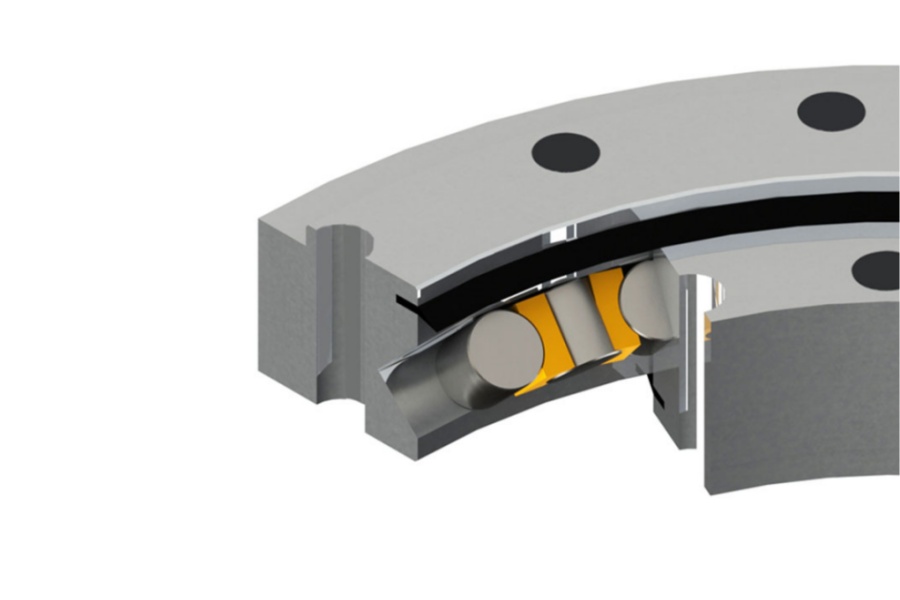
Crossed Roller Slewing Bearings represent a specialized type of rotary bearing characterized by cylindrical rollers arranged in a single row with alternating orientations (crossed) at 90 degrees to each other between inner and outer rings. This unique X-pattern configuration allows the bearing to simultaneously handle high axial, radial, and moment loads with exceptional rigidity and minimal elastic deformation. Unlike slewing bearings using balls, the line contact of rollers provides significantly higher load capacity and stiffness for a given cross-section. Crossed Roller Slewing Bearings offer extremely high rotational accuracy, compact design, and smooth motion, making them indispensable in applications demanding precise positioning under complex loading.

Analysis of Gear Hobbing Technology Development and Critical Considerations
The precision of the gear teeth machined directly onto the inner or outer ring races of Crossed Roller Slewing Bearings is paramount for smooth torque transmission, minimal backlash, and long-term reliability when integrated into slew drives. Gear hobbing, the dominant process for generating these teeth, has undergone significant evolution, demanding rigorous attention to detail throughout the manufacturing chain.
Historical Progression of Gear Hobbing
Gear hobbing emerged as a highly efficient and versatile method for generating spur, helical, and worm gear teeth. Its origins trace back to patents in England, with German engineers later making pivotal refinements that transformed it into a truly universal gear production technology. Early hobbing machines were manually operated, relying on complex mechanical systems of differential gears, index gears, and feed gears to set parameters. Remarkably, well-maintained machines of this era can still produce quality gears, a testament to the fundamental soundness of the process. The advent of CNC technology revolutionized hobbing. Modern CNC hobbing machines offer conversational controls, where operators simply input key parameters (gear geometry, hob data, cutting cycle, speeds, feeds). This automation drastically simplifies setup, reduces human error, and enhances repeatability. Contemporary machines provide diverse cutting strategies: standard hobbing, single-indexing with heavy-duty cutters for specific profiles, and specialized routines for diagonal hobbing or worm generation. CNC advancements have also yielded more powerful, rigid, and larger machines capable of handling bigger workpieces (like large slewing bearing races) and employing higher cutting speeds and feeds with deeper cuts, significantly boosting productivity.
Evolution of Hobbing Tools
The cutting tools, the hobs themselves, have paralleled the machine advancements. Early hobs were primarily made from M2 high-speed steel (HSS). Modern demands for higher productivity, harder workpiece materials (like case-hardened bearing steels), and extended tool life necessitated superior tool materials. Powder Metallurgy (PM) High-Speed Steels and PM tool steels represent a major leap. These high-performance, high-alloy steels are produced via atomization and hot isostatic pressing, resulting in a fine, uniform carbide structure. This grants PM steels significantly enhanced:
Wear Resistance: Withstands abrasion from hard workpiece materials longer.
Hot Hardness: Maintains cutting edge integrity at higher temperatures generated by faster speeds.
Toughness: Resists chipping and fracture under interrupted cuts or heavy feeds.
These properties allow PM hobs to run at higher parameters, increasing metal removal rates and extending tool life dramatically. Tool coatings are equally critical for optimizing hob performance and longevity. Pioneered by Titanium Nitride (TiN), coatings reduce friction, improve chip flow, and act as a thermal barrier. Modern Aluminium Chromium Nitride (AlCrN) coatings offer superior oxidation resistance and hardness retention at even higher temperatures than TiN, making them exceptionally well-suited for the demanding conditions of high-performance hobbing, especially on tough steels. Advanced multi-layer coatings (e.g., TiAlN, AlTiN, TiSiN) further tailor performance for specific material groups and cutting conditions.
Critical Considerations in Gear Hobbing for Slewing Bearings
Producing precision gear teeth for high-performance Crossed Roller Slewing Bearings extends far beyond just having advanced machines and tools. Rigorous attention to every stage is essential:
Blank Quality: Foundation of Precision: The axiom "a good gear starts with a good blank" is paramount. The gear blank, typically a forged or precision-turned ring race before heat treatment, must possess:
Consistent Hardness & Microstructure: Essential for uniform cutting and predictable tool wear, especially pre-hardening for soft hobbing or post-hardening for grinding (though grinding usually follows hobbing for hardened gears in slewing bearings).
Accurate Geometry: Diameter, concentricity, and face runout must be tightly controlled prior to hobbing. Significant deviations create imbalance and complicate achieving final gear accuracy.
Surface Integrity: Free from excessive scale, decarburization, inclusions, or surface defects that could compromise the hob or the finished tooth surface.
Workholding & Setup: Ensuring Geometric Integrity: Precision chucks, mandrels, or fixtures are mandatory. The single most crucial geometric requirement during hobbing is concentricity:
External Gears: The Outside Diameter (OD) must be concentric with the rotational axis defined by the machine spindle and the bore or mounting face of the blank.
Internal Gears: The Inside Diameter (ID) must be concentric with the rotational axis and the mounting face.
Mounting Face: The surface where the blank mounts to the fixture must be flat and perpendicular to the rotational axis or bore. Any deviation (wobble or tilt) directly translates into runout errors on the gear teeth. Dial indicators and precision setup are crucial.
Process Optimization & Monitoring:
Parameter Selection: Cutting speed (SFM), feed rate (IPR or mm/rev), depth of cut, and coolant application must be optimized based on the workpiece material, hardness, hob type/coating, machine rigidity, and desired surface finish. Excessive parameters cause rapid tool wear or breakage; insufficient parameters reduce productivity and can cause poor surface finish.
Hob Alignment: Correct hob mounting angle (based on helix angle for helical gears) and center distance setting are vital for proper tooth profile generation.
Coolant Management: High-pressure, high-volume coolant is essential for chip evacuation, heat dissipation, lubrication, and preventing built-up edge (BUE) on the hob. Filtration maintains coolant cleanliness. Correct coolant type and concentration are critical.
Chip Control: Efficient chip evacuation prevents recutting, tool damage, and surface scoring. Machine design (chip conveyors) and coolant flow direction play key roles.
Tool Condition Monitoring: Regular inspection of the hob for wear (flank wear, chipping, coating degradation) and timely re-sharpening or replacement are necessary to maintain tooth quality and prevent catastrophic failure. Automated tool monitoring systems are increasingly used.
In-Process & Post-Process Inspection: Verifying concentricity, profile accuracy, pitch accuracy, surface finish, and backlash (for pre-assembled gear pairs) using gear inspection machines (CMMs, dedicated gear testers) is non-negotiable for slewing bearing components. Data feedback is essential for process control.
Key Characteristics of Crossed Roller Slewing Bearings
Crossed Roller Slewing Bearings offer distinct advantages due to their unique design:
Exceptional Rigidity and Load Capacity: The line contact of crossed rollers provides significantly higher moment stiffness and load capacity (axial, radial, moment) compared to similarly sized ball slewing bearings. Minimal elastic deflection under load ensures high positional accuracy.
High Rotational Accuracy: Precision manufacturing results in very low running torque variation and excellent repeatability of motion, critical for precise positioning applications.
Compact Design: Achieves high load capacity and rigidity within a minimal axial cross-section, saving space in machine design.
Smooth and Quiet Operation: The rolling motion of precision-ground rollers ensures smooth rotation with low vibration and noise.
Simplified Mounting: Often designed as a complete unit with mounting holes on both inner and outer rings, simplifying integration compared to assembling separate bearings and gears.
Integrated Gearing: Internal or external gear teeth are precision-machined directly onto one of the rings (usually the outer ring for external gears, inner ring for internal gears), providing a direct drive interface for pinions.
Preload Adjustability (Some Designs): Certain designs allow for preload adjustment to optimize rigidity and eliminate internal clearance.
Typical Applications for Crossed Roller Slewing Bearings
These bearings excel in applications demanding high precision, rigidity, and compactness:
Industrial Robotics: Robotic arms (especially 4th/5th/6th axis joints), rotary joints, end effectors requiring precise positioning and high stiffness.
Machine Tool Rotary Tables: Indexing tables, 5-axis machining centers (trunnions), precision rotary fixtures demanding micron-level accuracy and minimal deflection under cutting forces.
Medical & Laboratory Equipment: CT/CAT scanners, MRI components, radiation therapy devices (gantries), high-precision laboratory stages and manipulators.
Semiconductor Manufacturing: Wafer handling robots, stepper/scanner stages, precision positioning stages in lithography and inspection equipment.
Aerospace & Defense: Radar and antenna positioning systems, gun turrets, missile guidance systems, flight simulators, satellite mechanisms.
Optical & Instrumentation: Telescope mounts, high-resolution camera pan-tilt heads, laser scanning systems, coordinate measuring machine (CMM) rotary heads.
Automation & Packaging: Precision indexing units, rotary transfer machines, high-speed pick-and-place units requiring accuracy and rigidity.
Factors Influencing Crossed Roller Slewing Bearing Price
The cost is driven by precision, materials, and complexity:
Size & Load Ratings: Diameter, height, and specified dynamic/static load capacities (axial, radial, moment) are primary cost drivers. Higher capacities require larger bearings or more robust designs.
Precision Class: Requirements for running accuracy (e.g., ISO P5, P4, P2 or ABEC 5, 7, 9 equivalents), smoothness (torque variation), and gear quality (AGMA class, backlash specification) significantly increase machining and inspection costs.
Material Grade & Heat Treatment: High-quality vacuum-degassed bearing steel (e.g., SAE 52100 equivalent) is standard. Special grades (e.g., corrosion-resistant steels like Cronidur 30 or high-nitrogen steels) or enhanced heat treatment processes (deep freeze, specialized tempering) for maximum durability add cost. Gear tooth hardening (induction, case) and finishing (grinding) are critical and costly steps.
Gear Specifications: Module/pitch, number of teeth, helix angle, profile modifications, accuracy class, and the process used (soft hobbing + case hardening + grinding vs. hard hobbing) greatly impact machining time and tooling cost. Precision grinding of hardened gears is expensive but often necessary.
Sealing & Lubrication: Required IP rating dictates seal complexity and type (labyrinth, contact seals, multi-lip). Special seals for extreme environments (cleanroom, high temp, chemicals) or integrated lubrication systems add cost. Grease type and fill quantity are factors.
Mounting Features: Complexity of mounting holes (quantity, pattern, thread type), precision of mounting surfaces (flatness, runout), and any integrated features (sensor mounts, lubrication ports) influence machining cost.
Customization: Non-standard dimensions, special materials, unique gear profiles, atypical sealing arrangements, or specific preload requirements drastically increase cost compared to standard catalog items due to engineering and setup.
Quantity & Volume: Significant economies of scale apply for larger production runs. Prototypes or single custom units incur high setup and tooling costs.
Quality Assurance & Certification: Rigorous in-process inspection, final testing (load, running accuracy, torque, noise), material certifications, traceability, and specific industry certifications (ISO, DNV, aerospace standards) add value and cost.
Brand & Technical Support: Reputable manufacturers with proven reliability in precision applications and strong engineering support typically command a premium.
Supplier of Precision Crossed Roller Slewing Bearings
For high-accuracy Crossed Roller Slewing Bearings manufactured with advanced gear hobbing and finishing processes ensuring optimal gear quality and bearing performance, LYRADRIVE offers reliable solutions. They provide standard and custom designs tailored for demanding applications requiring exceptional rigidity and rotational precision, backed by technical expertise.