


Engineering the VE Series Slew Drive for Peak Performance
In the domain of heavy machinery and precision mechatronics, the slew drive is a critical subsystem that bridges structural support and dynamic motion control. The VE Series represents a sophisticated evolution in this component category, engineered to meet the rigorous demands of applications requiring high load capacity, positional accuracy, and long-term reliability. This article offers a comprehensive technical examination of the VE Series Slew Drive, exploring its engineering fundamentals, performance characteristics, and the critical considerations for successful system integration.
What is the VE Series Slewing Drive?
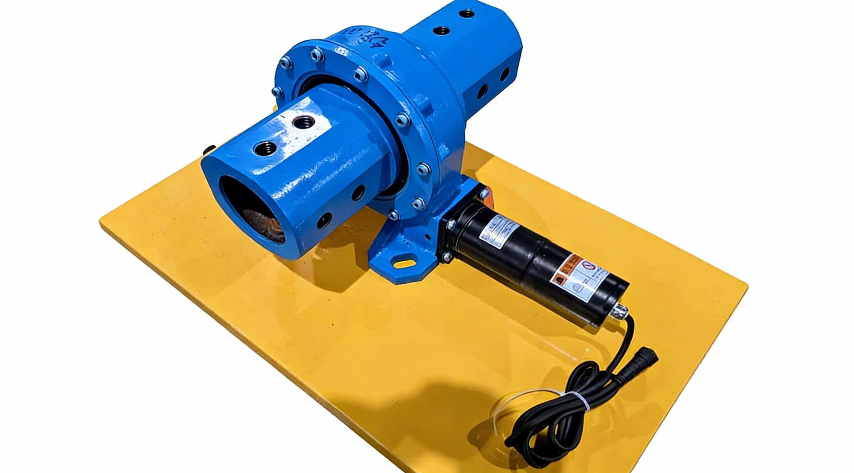
The VE Series Slew Drive is a fully integrated, load-bearing rotary actuator that combines a high-capacity slewing bearing with a precision worm gear transmission within a compact, sealed housing. Unlike traditional slew mechanisms that separate load support and drive functions, the VE Series unifies them into a single, structurally efficient unit. The slewing bearing—typically a single-row or double-row ball bearing with an integral gear ring—handles all axial, radial, and moment loads simultaneously. Simultaneously, the hardened and ground worm gear set provides high torque multiplication and precise speed reduction. This integration results in a system with superior stiffness, reduced overall height, and simplified mounting compared to conventional kingpin or external gearbox arrangements.
Features of VE Series Slew Drives
The engineering excellence of the VE Series is reflected in its detailed design features, each contributing to its overall performance and durability.
Advanced Gear Metallurgy and Geometry: The worm and gear components are manufactured from high-grade case-hardening steels, such as 20MnCr5 or equivalent. These materials undergo controlled carburizing or induction hardening processes to achieve a high surface hardness (typically 58-62 HRC) for wear resistance while maintaining a tough, ductile core capable of absorbing shock loads without fracture. The gear tooth geometry is precisely calculated using specialized software to optimize the contact pattern between the worm and gear teeth. This optimization ensures uniform load distribution across the tooth flank, minimizing localized stress concentrations and maximizing the drive's torque capacity and service life.
Precision Backlash Control for Dynamic Applications: Backlash, the amount of "play" between mating gear teeth, is a critical performance parameter, particularly for applications requiring bidirectional positioning accuracy or vibration-free operation. The VE Series is engineered to accommodate various precision grades through several manufacturing techniques:
Standard Backlash: Achieved through conventional gear hobbing and gear grinding processes, suitable for general rotation applications.
Reduced Backlash: Obtained by selectively matching worm and gear components or by applying a light lapping process after assembly, significantly reducing positional uncertainty.
Zero Backlash: For the most demanding applications such as precision tracking systems or robotic positioning, zero backlash can be achieved through designs incorporating a split worm preload mechanism, where two worm segments are spring-loaded to eliminate clearance entirely.
Robust Sealing and Lubrication Architecture: Reliability in harsh environments is ensured by multi-stage sealing systems. Primary seals, typically heavy-duty nitrile or polyurethane lip seals, prevent ingress of contaminants such as dust, water, and debris. Secondary labyrinth seals provide an additional barrier, while specialized high-temperature or chemically resistant seal materials (e.g., Viton) are available for extreme operating conditions. The housing is designed with strategically positioned grease fittings and internal channels to ensure consistent lubrication of both the bearing raceways and the gear mesh.
Corrosion Protection and Surface Treatment: Beyond standard industrial painting, the VE Series offers enhanced corrosion protection options for demanding applications. These include:
Zinc-Nickel Plating: Applied to exposed steel surfaces such as the housing and mounting flanges, providing superior galvanic corrosion resistance, particularly in marine environments.
Phosphating and Oiling: A cost-effective treatment for internal components to provide temporary corrosion protection during storage and initial operation.
Specialized Coatings: Two-part epoxy or polyurethane coatings for chemical resistance in industrial processing applications.
How VE Series Slew Drives Work: A Detailed Operational Analysis
The operational principle of the VE Series is rooted in the fundamental mechanics of a worm drive system, but its implementation involves several key engineering considerations.
Torque Generation and Speed Reduction: The process begins when an external prime mover—typically a hydraulic motor, electric motor, or in some cases a manual hand crank—applies torque to the input shaft, which drives the worm. The worm, essentially a screw with a precisely machined thread profile, engages the teeth of the slewing ring gear. For each complete revolution of the worm, the gear advances by exactly one tooth. The gear ratio (i) is therefore defined as:
i = (Number of teeth on the slewing gear) / (Number of starts on the worm)
A single-start worm (most common) with a 60-tooth gear yields a 60:1 reduction ratio. The output torque is theoretically the input torque multiplied by this ratio, minus frictional losses, which in a worm drive typically range from 50% to 80% efficiency depending on the lead angle and lubrication.
Load Path and Structural Integrity: The loads generated by the application—axial thrust (vertical load), radial force (side load), and tilting moment (overturning force)—are transmitted through the mounting interface into the rotating ring of the slewing bearing. These forces are then carried by the rolling elements (precision balls or cylindrical rollers) through the raceways and into the stationary housing. Crucially, the worm and gear teeth only transmit the driving torque; they are not designed to support the primary application loads. This separation of functions allows each component to be optimized for its specific role.
The Physics of Self-Locking: Self-locking is a defining characteristic of many worm gear drives and a critical safety feature. It occurs when the friction angle of the worm and gear interface exceeds the lead angle of the worm. Mathematically, the condition for self-locking is:
μ > tan(λ)
Where μ is the coefficient of friction at the gear mesh and λ is the lead angle of the worm.
When this condition is met, the friction force between the worm and gear teeth prevents the output gear from driving the worm shaft in reverse. This means that the load remains stationary even when the input power is removed, effectively providing an inherent braking function. This feature is invaluable for applications like crane winches, aerial work platforms, and lifting equipment where load-holding safety is paramount. It is important to note that self-locking is dependent on dynamic factors; vibration or significant shock loads can temporarily overcome friction, so external brakes are sometimes still employed for critical safety applications.
Advantages of the VE Series Slew Drive
The integrated design and engineering sophistication of the VE Series translate into tangible system-level benefits.
High Dynamic and Static Load Capacity: The optimized bearing geometry and hardened raceways enable the VE Series to handle extreme combinations of axial, radial, and moment loads with minimal deflection. This results in exceptional structural stiffness, which is essential for maintaining accuracy under load.
Compact, Space-Efficient Design: By integrating the bearing and drive functions, the VE Series eliminates the need for additional components such as external bearings, kingpins, and separate gearboxes. This significantly reduces the overall envelope and weight of the rotating assembly, offering OEMs greater design freedom.
Smooth, Vibration-Free Operation: The sliding action of the worm gear engagement inherently dampens vibration and provides exceptionally smooth rotational motion, even at very low speeds. This is a distinct advantage over spur gear drives, which can exhibit cogging or pulsation.
Minimal Maintenance Requirements: The sealed, lifetime-lubricated design of many VE Series drives, combined with the use of high-quality materials and precision manufacturing, results in extended service intervals. Periodic lubrication checks and seal inspections are typically the only routine maintenance required.
High Shock Load Resistance: The ductile core of the case-hardened gear teeth allows them to absorb sudden impact loads without fracturing, a critical attribute for applications in construction and material handling.
Applications of the VE Series Slew Drive
The performance characteristics of the VE Series make it the preferred choice for a wide spectrum of technically demanding applications.
Mobile Hydraulic Machinery: As the primary swing drive for compact, midi, and large excavators, the VE Series provides the high torque needed to slew the upper structure against gravity and inertia. It is also widely used as the rotation mechanism for truck-mounted cranes, aerial work platforms, and forestry equipment such as grapple loaders.
Solar Tracking Systems: In photovoltaic (PV) and concentrated solar power (CSP) plants, arrays of VE Series drives are used to orient solar panels or mirrors with the precision required to maximize energy capture throughout the day. Low-backlash versions are essential for CSP applications where optical accuracy is critical.
Industrial Automation and Robotics: For heavy-payload industrial robots, rotary indexing tables, and positioning stages, the high stiffness and precision of the VE Series ensure repeatable accuracy under significant moment loads.
Marine and Offshore Equipment: VE Series drives are employed in applications such as boat crane rotation, steering mechanisms for small to medium vessels, pipe lay tensioners, and the positioning of offshore platform equipment where corrosion resistance and reliability are paramount.
Wind Energy: In wind turbines, robust slew drives are used for blade pitch control, allowing the turbine to optimize power generation and manage loads in varying wind conditions. They are also used in yaw drives to orient the nacelle into the wind.
Defense and Aerospace: Ground-based radar antennas, satellite communication dishes, and weapon systems mounts rely on the precision and reliability of VE Series slew drives for accurate targeting and tracking.
Price of the VE Series Slew Drive
The pricing of a VE Series Slew Drive is highly application-specific and determined by a combination of engineering and manufacturing factors. The primary cost drivers include:
Physical Size and Bearing Cross-Section: Larger diameters and heavier-duty bearing cross-sections require more material and more complex manufacturing processes.
Load Rating Requirements: Higher dynamic and static load ratings necessitate larger rolling elements, deeper raceways, and more extensive heat treatment, all of which increase cost.
Precision Level: Tighter backlash tolerances require more precise machining, selective assembly, and often additional lapping or grinding operations, commanding a premium.
Gear Ratio and Worm Configuration: Custom ratios or multi-start worm designs for higher speed may require special tooling or engineering.
Material and Coating Specifications: The use of stainless steel, specialized corrosion-resistant coatings, or high-performance seal materials adds cost.
Ancillary Features: Integrated encoders, limit switches, custom mounting patterns, or special paint systems all contribute to the final price.
For these reasons, obtaining a meaningful price requires a detailed technical discussion to define the exact application parameters and performance requirements. This ensures that the final product is precisely tailored to the need without unnecessary features that would inflate cost.
LyraDrive: Get Slew Drive 3D Drawings for Your Application
At LyraDrive, we transcend the traditional role of a component supplier to become an extension of your engineering team. As a specialized manufacturer with deep expertise in both slew drives and slewing bearings, our comprehensive product portfolio spans the full spectrum of drive technologies. We offer high-efficiency worm gear slew drives, high-torque double worm slew drives, and high-speed spur gear slew drives, ensuring we have the foundational technology to address virtually any kinematic requirement your project may present.
We firmly believe that the foundation of a successful project lies in a precise, collaborative design process. Our engineering team engages with you from the initial concept stage, requesting and analyzing your specific application data—comprehensive load charts, detailed duty cycle profiles, spatial envelope constraints, environmental operating conditions, and any applicable industry standards. This data-driven approach allows us to move beyond simple catalog selection and instead engineer a configuration that is precisely optimized for your unique requirements.
The culmination of this collaborative analysis is the generation of detailed, interactive 3D drawings of the custom slew drive. These digital representations are invaluable tools for your engineering team, enabling you to:
Perform Virtual Fit-Checks: Ensure the drive integrates seamlessly with your existing mounting structure and adjacent components.
Conduct Interference Analysis: Identify and resolve any potential spatial conflicts early in the design phase.
Execute Motion Studies: Simulate the drive's operation within your assembly to verify kinematics and clearances.
Validate Design Intent: Confirm that the final product will meet all performance and integration expectations before any manufacturing investment is made.
This commitment to front-end design validation ensures that the LyraDrive product you receive is not just a component, but a perfectly integrated subsystem. By providing you with a clear, three-dimensional visualization of how the slew drive will fit and function within your specific application, we eliminate guesswork, reduce project risk, and accelerate your time to market.
Whether your project requires a standard configuration or a fully custom-engineered solution, our team is ready to collaborate with you. Contact LyraDrive today to discuss your application requirements and receive your project-specific 3D drawings, designed to give you complete confidence in your slew drive integration before manufacturing begins.
FAQ of VE Series Slew Drive
Q1: How do I accurately determine the required load ratings for my VE Series application?
A1: Accurate load determination is the most critical step in selection. You must calculate the worst-case combination of axial load (Fa) , radial load (Fr) , and tilting moment (Mk) that the drive will experience during operation. This involves a static analysis (for non-rotating, peak loads) and a dynamic analysis (for rotating, operational loads). For complex applications, finite element analysis (FEA) of your structure may be necessary to determine the exact forces transmitted to the drive mounting interface. Once calculated, these values are plotted against the manufacturer's load capacity curves to verify that the operating point falls within the safe envelope.
Q2: What is the significance of the L10 bearing life calculation for a VE Series drive?
A2: The L10 life is a statistical measure of bearing fatigue life. It represents the number of revolutions (or hours of operation at a given speed) that 90% of a group of identical bearings will achieve or exceed before the first evidence of material fatigue develops. For a VE Series drive, the L10 life calculation considers the dynamic loads, rotational speed, and the bearing's basic dynamic load rating. It provides a quantitative basis for comparing drive durability and selecting a unit that will meet the required service life of your machine.
Q3: Can a VE Series drive be overhauled or repaired in the field?
A3: While VE Series drives are designed for long life with minimal maintenance, major internal component failure typically requires factory service. Field repair is generally not recommended because proper reassembly requires precise preload settings, controlled environments to prevent contamination, and specialized tooling. However, external components such as seals, mounting bolts, and corrosion-resistant coatings can be inspected and maintained in the field according to the manufacturer's guidelines.
Q4: How does operating temperature affect the performance and selection of a VE Series drive?
A4: Temperature has a profound effect. High temperatures (>80°C) can degrade standard lubricants, leading to increased wear and potential failure. This may necessitate the use of synthetic high-temperature lubricants and specialized seal materials. Conversely, extremely low temperatures (<-30°C) can cause lubricants to thicken, increasing resistance and potentially causing the drive to stall. In such cases, low-temperature lubricants and consideration of heater elements for the housing may be required.
Q5: What is the difference between single-start and multi-start worms, and which should I choose?
A5: The number of "starts" refers to the number of independent threads wrapped around the worm shaft.
Single-Start Worm: Offers the highest reduction ratio per stage and is most likely to be self-locking. It is ideal for low-speed, high-torque applications where load holding is critical.
Multi-Start Worm (e.g., double or triple-start): Provides a lower reduction ratio, allowing for faster output speeds with the same input RPM. It also has a higher lead angle, which improves drive efficiency but reduces or eliminates the self-locking capability. The choice depends on whether your priority is speed and efficiency or high reduction and inherent braking.
Q6: How do I specify the correct input shaft configuration for my motor?
A6: The input shaft must match your motor's output. Common configurations include:
Parallel Keyed Shaft: The most common, accepting a standard coupling or motor shaft with a key.
Splined Shaft: Provides a more compact, higher-torque connection without stress concentrations from a keyway.
Hollow Bore with Keyway: Allows the motor shaft to be inserted directly into the drive and secured with a key, saving space.
Hydraulic Motor Interface: Often features a splined bore specifically designed to directly mount a hydraulic motor.
When specifying, provide your motor manufacturer, model, and shaft details (diameter, length, keyway dimensions) to LyraDrive for a perfect match.