


What is a Spur Gear Slew Drive?
A Spur Gear Slew Drive is a highly efficient integrated rotary assembly driven by a pinion meshing directly with a slewing bearing. Engineered for high speeds and continuous 360-degree rotation, it delivers exceptional mechanical efficiency (over 90%) with low heat generation. Without inherent self-locking, it allows smooth back-driving and rapid, high-frequency positioning.
At present, the product designed and produced by our company is mainly divided into three series: light load, medium load and heavy load. The product can be customized according to the actual situation of the host.
Talk to the Engineer
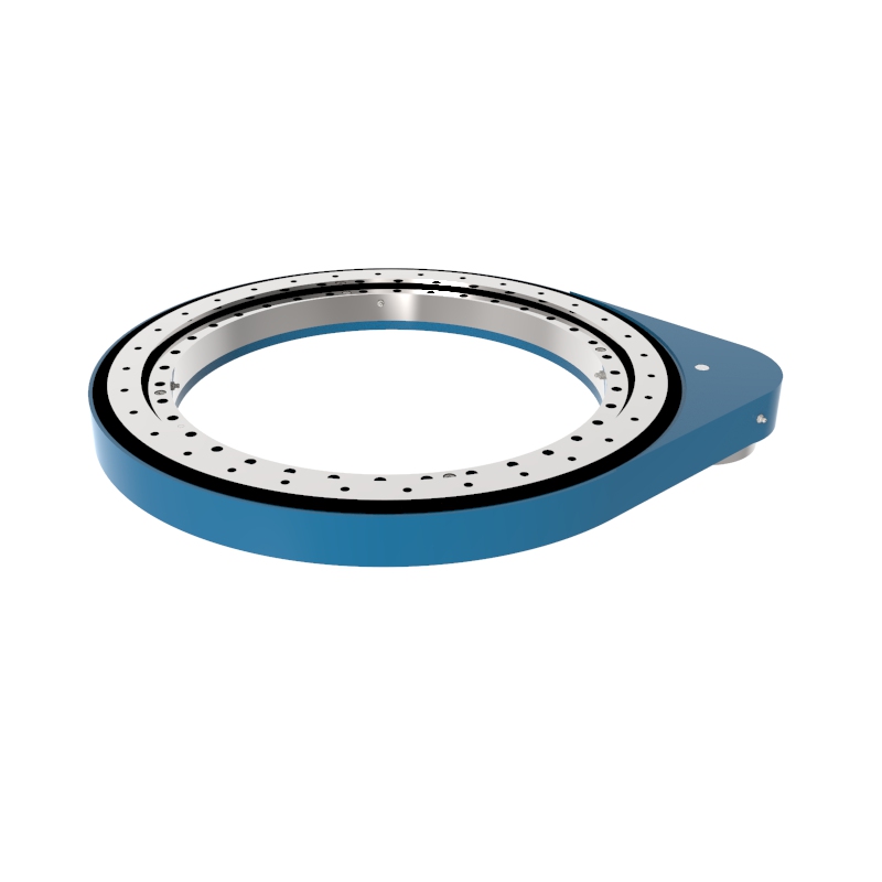
Medium Duty Gear Slewing Drive SP-M 0741
The SP-M 0741 gear slewing drive uses precision spur or helical gears in a stable base design for efficient, high-speed, high-precision automatic slewing in industrial machinery.
Read More Get A Quote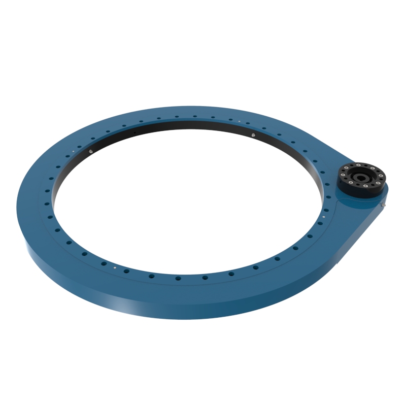
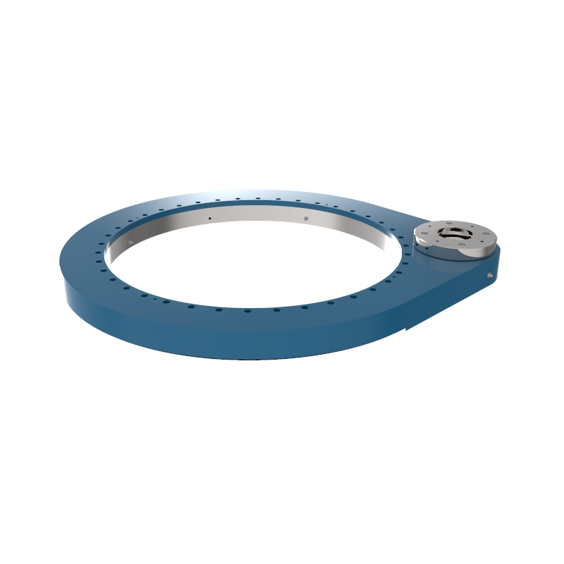
Medium Duty Gear Slewing Drive SP-M 0841
The SP-M 0841 gear slewing drive uses precision spur or helical gears in a stable base design for efficient, high-speed, high-precision automatic slewing in industrial machinery automation.
Read More Get A Quote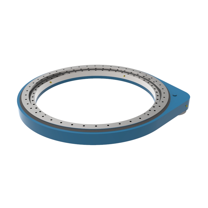
Medium Duty Gear Slewing Drive SP-M 0941
The SP-M 0941 gear slewing drive uses precisely machined spur or helical gears in a compact base for efficient, high-speed, high-precision automatic slewing in industrial machinery.
Read More Get A Quote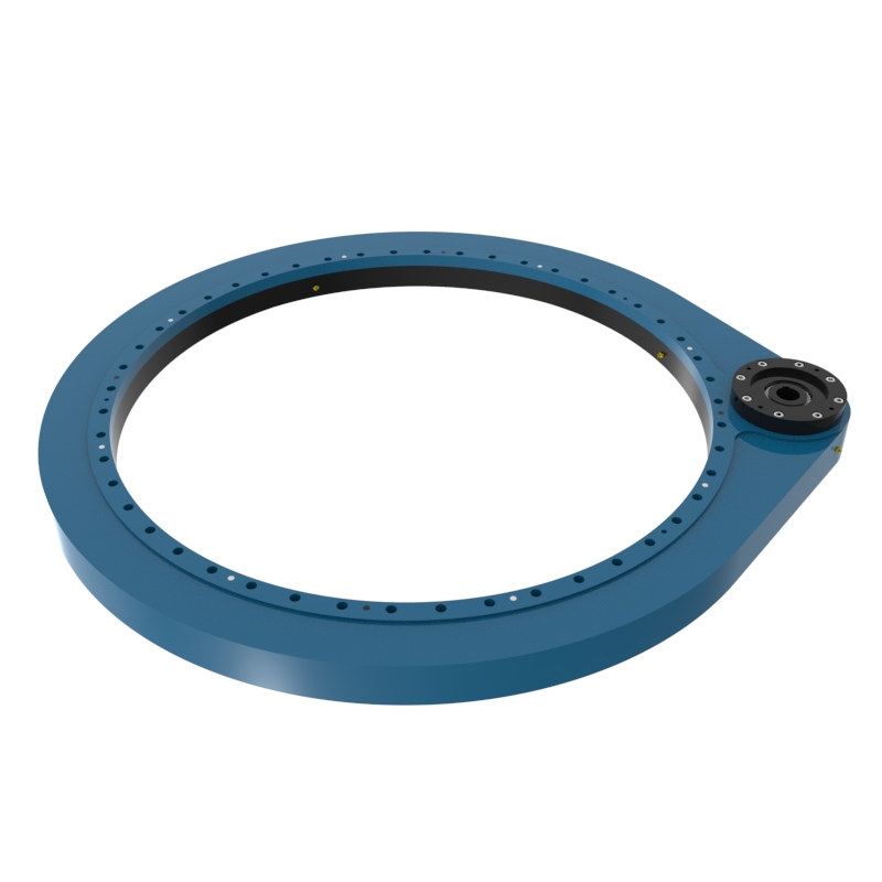
Medium Duty Gear Slewing Drive SP-M 1091
The SP-M 1091 gear slewing drive uses precision spur or helical gears in a stable base design for efficient, high-speed, high-precision automatic slewing in industrial machinery.
Read More Get A Quote
Heavy Duty Gear Slewing Drive SP-H 0455
The SP-H 0455 gear-type slewing drive uses precision spur or helical gears in a compact, stable base design for efficient heavy-duty reduction in cranes and rotating platforms where space is limited.
Read More Get A Quote
Heavy Duty Gear Slewing Drive SP-H 0555
The SP-H 0555 gear slewing drive uses precision spur or helical gears in a stable base design for efficient heavy-duty reduction in cranes and rotating platforms where space is limited and high precision is required.
Read More Get A Quote
Heavy Duty Gear Slewing Drive SP-H 0955
The SP-H 0955 gear slewing drive (8 mm module) delivers efficient heavy-duty precision reduction via spur/helical gears in a compact, stable design for cranes and rotating platforms.
Read More Get A Quote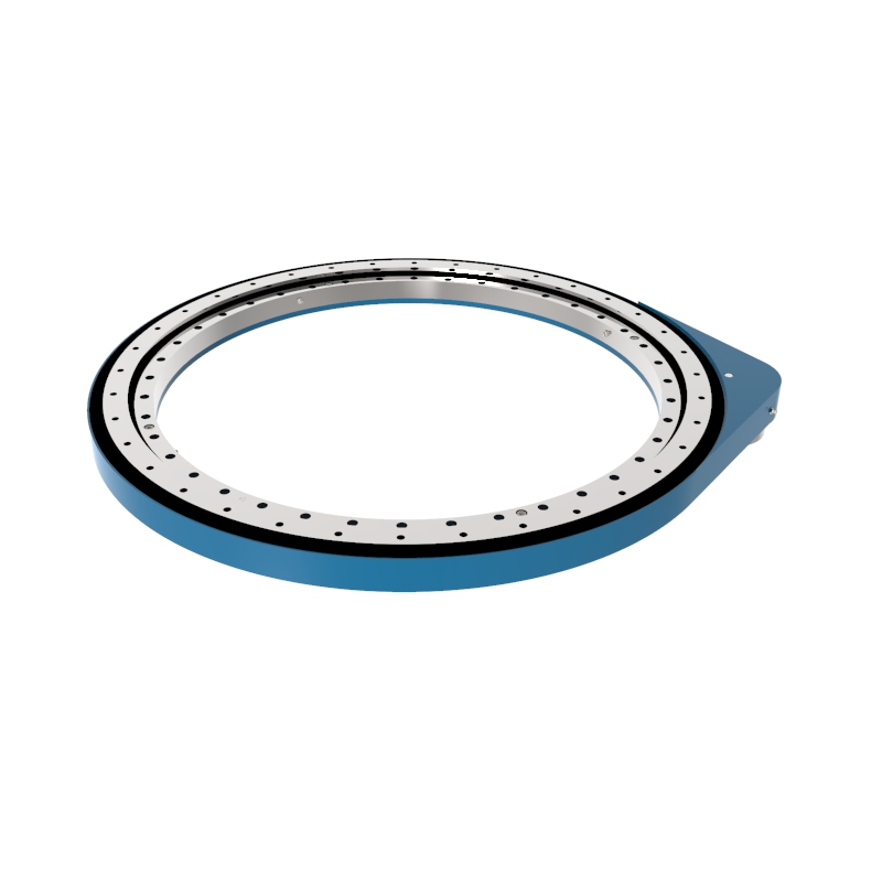
Heavy Duty Gear Slewing Drive SP-H 0855
The SP-H 0855 gear slewing drive uses precision spur or helical gears in a stable base design for efficient heavy-duty reduction in cranes and heavy machinery platforms where space is limited and high precision is required.
Read More Get A Quote
Heavy Duty Gear Slewing Drive SP-H 0755
The SP-H 0755 gear slewing drive delivers efficient heavy-duty precision reduction via spur/helical gears in a compact, stable base design for cranes and rotating platforms.
Read More Get A Quote
Heavy Duty Gear Slewing Drive SP-H 0655
The SP-H 0655 gear slewing drive uses precision spur or helical gears in a stable base design for efficient heavy-duty reduction in cranes and heavy machinery platforms where space is limited and high precision is required.
Read More Get A Quote
Lightweight Slewing Ring Gear Drive SP-I 0941
SP-I 0941 gear slewing drive is a highly efficient gear reduction transmission device, which is widely used in the automatic slewing of industrial machinery, especially in the occasions that require high precision and high speed.
Read More Get A Quote
What is a Spur Gear Slew Drive?
A Spur Gear Slew Drive is a modular, high-speed rotary transmission system that utilizes direct pinion-to-gear meshing. It consists of a small driving pinion gear that directly engages with the teeth of a large slewing bearing, all housed within an integrated structure. Optimized for efficiency and speed, this heavy-duty drive converts input power into smooth, continuous, and high-velocity 360-degree rotational output under complex multi-directional loads.Key Features of Spur Gear Slew Drive
High Mechanical Efficiency: Delivers exceptional power transmission efficiency (typically ≥90%) due to rolling contact, minimizing energy loss and heat generation. This ensures that almost all input power is directly converted into rotational torque.
High Rotational Speed: Engineered for high-velocity operations, allowing for much faster continuous rotation compared to worm gear alternatives. It easily handles continuous high-RPM motor inputs without overheating the internal gears.
Reversible Back-Driving: Lacks inherent self-locking, enabling the drive to be driven smoothly in reverse by external loads when power is cut. This is critical for applications requiring manual override or mechanical yielding.
Precise Micro-Positioning: Offers low-backlash configurations and high torsional stiffness, ensuring crisp response times and sharp positioning repeatability. The direct drive teeth eliminate lag, translating motor encoder signals into exact angular movements.
Compact All-In-One Footprint: Integrates the pinion, heavy-duty bearing, and lubrication channels into a single, compact housing. This saves valuable structural space and drastically reduces the engineering hours needed for machine assembly.
How Does a Spur Gear Slew Drive Work?
A spur gear slew drive operates on the principle of direct parallel-axis gear meshing. Unlike worm gear drives that transfer power at a 90-degree angle using a screw-like sliding motion, a spur slew drive utilizes direct, tooth-to-tooth rolling contact between parallel shafts to maximize speed and energy efficiency.
Here is the step-by-step breakdown of how the mechanism functions:
1. Direct Power Input
The process begins when an external motor (such as a high-speed AC/DC motor, servo motor, or hydraulic motor) is activated. The motor shaft connects directly to a small driving gear known as the pinion, initiating high-speed rotation.
2. Parallel Pinion-to-Bearing Meshing
The straight teeth of the pinion mesh directly with matching teeth cut into either the outer or inner ring of a large slewing bearing. As the pinion rotates, it transfers mechanical force directly along parallel planes without changing the axis angle.
3. Low-Friction Rolling Contact
The gear teeth engage via rolling contact rather than sliding friction. This rolling action keeps mechanical resistance and heat generation to an absolute minimum, allowing the drive to convert over 90% of the input energy into output torque.
4. Multi-Load Management
While the gear teeth handle the rotation, the integrated heavy-duty slewing bearing manages the structural weight. Internal rows of steel balls or rollers absorb massive axial loads, radial loads, and overturning tilting moments simultaneously to ensure perfectly stable rotation.
5. Non-Self-Locking & Back-Driving
Because internal friction is extremely low, a spur gear slew drive does not self-lock. When power is cut, external loads can smoothly push the drive in reverse. For B2B applications requiring the drive to hold a strict static position, an electronic or hydraulic brake is integrated onto the input motor.
Structural Composition of a Spur Gear Slew Drive
A spur gear slew drive features a highly integrated, modular design. By enclosing all critical moving parts into a singular assembly, it reduces the overall structural footprint and simplifies machine installation for B2B buyers.
The core mechanical components that make up the drive include:
Driving Pinion: The small, precision-machined straight gear attached directly to the motor input shaft. It acts as the primary driving force that transfers rotational torque directly to the main bearing gear ring.
Slewing Bearing / Ring: The heavy-duty structural foundation of the drive. It features integrated straight gear teeth cut into either its internal or external circumference that mesh perfectly with the driving pinion.
Rolling Elements: Rows of high-strength steel balls or cylindrical rollers situated inside the slewing bearing raceways. They absorb and distribute multi-directional axial, radial, and tilting loads during high-speed rotation.
Enclosed Enclosure / Housing: A rugged, cast-iron or aluminum alloy shell that encapsulates the gear setup. It protects internal components from harsh outdoor debris and serves as the structural mounting base for connected equipment.
Sealing System: Advanced, heavy-duty oil and dust seals lining the rotating interfaces. They prevent internal lubrication grease from leaking while keeping water, sand, and dust out to achieve high IP protection ratings.
Motor Adapter Flange: A standardized, precision-drilled interface plate on the housing. It allows industrial clients to seamlessly bolt on global motor brands, including hydraulic motors, AC/DC electric motors, and servo motors.
Selection Considerations of a Spur Gear Slew Drive
Selecting the ideal spur gear slew drive requires a precise evaluation of your application’s dynamic forces and operational demands. Because spur drives are engineered for high-speed, high-efficiency, and non-self-locking operations, B2B buyers must prioritize the following five technical considerations:
Dynamic Load and Overturning Moment Calculations
Unlike static positioning systems, spur drives often operate under continuous motion, making dynamic calculations vital. You must determine:
Tilting Moment : The severe overturning torque generated when a heavy load extends outward from the center of rotation. This dictates the structural size of the slewing bearing.
Axial and Radial Loads: The combined vertical weight and horizontal forces (such as rapid centrifugal forces or sudden crosswinds) acting on the unit during high-speed rotation.
Operating Speed and Duty Cycle
Spur gear drives excel at high rotational velocities compared to worm gears. However, continuous operation generates mechanical demands:
Rotational Velocity (RPM): Define your required operating speed. Higher speeds increase internal structural stress and impact bearing lifecycles.
Duty Cycle: Determine if the drive operates on an intermittent basis or runs 24/7 on a factory floor. High duty cycles require explicit thermal dissipation planning and premium wear-resistant tooth treatments.
Braking and Holding Torque Requirements
Because spur gear teeth mesh straight-on, the system does not self-lock. External forces can easily back-drive the mechanism when the motor stops.
Brake Integration: If your application must hold a strict position under load (such as a crane boom or an aerial lift), you must select an input motor equipped with an integrated fail-safe electronic or hydraulic brake.
Holding Torque Rating: Ensure the combined motor brake and gear reduction can withstand the maximum static external forces without slipping.
Gear Backlash and Positioning Accuracy
For automated and robotic applications, minimizing gear play is critical for precise targeting:
Standard Backlash: Perfect for heavy construction attachments, log grabbers, and standard rotating platforms where minor play does not disrupt operations.
Precision / Low Backlash: Mandatory for high-frequency robotic joints, automated welding positioners, and dual-axis solar trackers to ensure exact repeatable positioning and eliminate mechanical lag.
Pinion and Gear Ring Tooth Hardening
High-speed rolling contact can induce rapid localized wear if the gear metallurgy is insufficient:
Induction Hardening: Ensure that both the driving pinion and the slewing ring teeth have undergone precise surface induction hardening (typically to 50–60 HRC). This treatment dramatically boosts fatigue resistance and prevents premature tooth pitting under heavy shock loads.
The Difference Between Spur Gear & Worm Gear Slew Drives
When designing an industrial rotation system, selecting the correct gear configuration is vital for optimizing performance, safety, and operational longevity.The comparison table below details the core technical differences between Spur Gear Slew Drives and Worm Gear Slew Drives to help you select the ideal solution for your specific application requirements:
| Comparison Factor | Spur Gear Slew Drive | Worm Gear Slew Drive |
|---|---|---|
| Operating Speed | High-speed capabilities; engineered for fast, smooth, and continuous rotation. | Low-speed restrictions; designed for slow, controlled rotation or intermittent tracking. |
| Transmission Efficiency | Very high efficiency; direct gear meshing results in minimal friction and low heat generation. | Lower efficiency; sliding friction between worm threads and gear teeth generates more heat. |
| Self-Locking Ability | No inherent self-locking; requires an external motor brake to hold payloads securely in place. | Excellent reverse self-locking safety; mechanically prevents unpowered back-driving. |
| Gear Ratio Range | Lower reduction ratios; suitable for applications requiring quick responsiveness and agility. | High reduction ratios; ideal for delivering massive output torque from small inputs. |
| Gear Orientation | Parallel axis setup; the input motor shaft runs parallel to the output rotation axis. | Perpendicular (90°) setup; allows for an incredibly compact, space-saving installation footprint. |
| Best Application | Rapid positioning systems, continuous automation lines, high-frequency machinery, and fast-rotation equipment. | Heavy-lift cranes, solar trackers, aerial platforms, and heavy-duty, safety-critical locking environments. |
Advantages of a Spur Gear Slew Drive
Efficiency: Spur gears are more efficient than worm gears, particularly at higher speeds, because they have less friction and heat generation during operation.
Speed: They can handle higher rotational speeds than worm gear slew drives due to their efficient power transmission.
Cost-Effectiveness: Generally, spur gears are simpler and cheaper to manufacture compared to worm gears.
Backdrivability: While this can be a disadvantage in some applications, the ability to backdrive can be beneficial in scenarios where manual movement of the driven load is necessary.
Disadvantages of a Spur Gear Slew Drive
Noise: Spur gears are typically noisier than worm gears, especially at high speeds.
Backdrivability: In applications where holding torque is crucial (like in some lifting operations), the natural backdrivability of spur gears can be a drawback as it might require additional braking or locking mechanisms.
Typical Applications of Spur Gear Slew Drives
High-Speed Industrial Automation & Robots
Perfect for robotic arms, automated material handling systems, and fast-indexing conveyor lines that demand continuous, high-frequency rotation and rapid cycle times.
Precision Rotary Tables & Positioners
Widely used in factory welding positioners, CNC machining turntables, and assembly fixtures where components must be indexed quickly, smoothly, and precisely to a specific angle.
Packaging and Bottling Machinery
Integrated into high-speed filling, labeling, and packaging carousels that operate continuously under light-to-medium loads but require extreme velocity and smooth mechanical efficiency.
Amusement Park Rides & Stage Equipment
Utilized in revolving stages, theater lighting rigs, and dynamic components of amusement rides where fast, low-friction, and highly fluid rotational movement is essential for performance.
Water & Wastewater Treatment Equipment
Deployed in the central driving mechanisms of large clarifiers, thickeners, and rotary scrapers that run continuously over long periods, benefiting from the drive’s high transmission efficiency and low heat generation.
Logistics & AGVs (Automated Guided Vehicles)
Found in the heavy steering and drive modules of automated warehouse vehicles, transfer carts, and mobile gantry systems requiring nimble, highly responsive directional changes.
Spur Gear Slew Drive Installation and Operation Manual
Before installing the Spur Gear Slew Drive, please read this manual. This manual contains essential information for proper installation and maintenance. All following procedures must be performed by qualified personnel. For technical issues, contact our after-sales service immediately.
Transportation and Handling: During transportation, ensure the Spur Gear Slew Drive packaging is oriented correctly to avoid impacts. Wear work gloves when handling and operate with care. The Spur Gear Slew Drive typically has threaded holes on the outer ring. Use at least three lifting eyes with a hoisting device for safe handling.
Storage: Store the Spur Gear Slew Drive in its original packaging, placed in a dry, ventilated area. In sealed packaging, the anti-rust protection lasts 6 months. For longer storage, take additional protective measures.
Pre-Installation Checks: Inspect the Spur Gear Slew Drive for physical damage. Clean the Spur Gear Slew Drive and mounting brackets, removing debris (e.g., metal shavings, burrs, paint, welding slag).
Cleaning Anti-Rust Oil: Use cleaning solvents (e.g., diesel, gasoline) to remove anti-rust oil from external surfaces. Avoid solvents that degrade rubber seals. Follow solvent safety guidelines for worker protection.
Bolt Selection: Our company does not supply assembly bolts. The following are recommendations only: Select bolts of correct size, type, and strength grade. Minimum bolt grade: 8.8. Thread engagement length: 2× nominal bolt diameter. Avoid bolt protrusion beyond threads to prevent interference or damage. If contact stress exceeds limits, use high-strength washers.
Bolt Tightening Torque (Values in N·m)
| Bolt Size | 8.8 Grade | 10.9 Grade | 12.9 Grade | Bolt Size | 8.8 Grade | 10.9 Grade | 12.9 Grade |
|---|---|---|---|---|---|---|---|
| M4 | 2.25 | 3.31 | 3.87 | M16 | 168.00 | 246.00 | 288.00 |
| M5 | 4.16 | 6.77 | 7.92 | M18 | 229.00 | 336.00 | 394.00 |
| M6 | 7.80 | 11.50 | 13.40 | M20 | 327.00 | 481.00 | 562.00 |
| M8 | 19.10 | 28.00 | 32.80 | M22 | 450.00 | 661.00 | 773.00 |
| M10 | 38.00 | 55.80 | 65.30 | M24 | 565.00 | 830.00 | 972.00 |
| M12 | 66.50 | 97.70 | 114.00 | M27 | 837.00 | 1230.00 | 1439.00 |
| M14 | 107.00 | 156.00 | 183.00 | M30 | 1131.00 | 1661.00 | 1944.00 |
Spur Gear Slew Drive Installation
Follow these steps to avoid internal stress or installation issues:
Apply thread-locking adhesive.
Pre-tighten bolts crosswise. Start at the inner/outer ring, tighten diagonally to 30% torque, then 50%, and finally 100%.
Install all bolts. If structural constraints prevent full installation, seal unused holes (e.g., with silicone) to prevent water/dust ingress.
Ensure bolt length does not interfere with rotation.
Mark bolt heads and joints after tightening to check for loosening later.
Lubrication Specifications
Critical components are pre-lubricated with Mobil EP2 grease. Re-lubricate during installation if needed: Gear raceway (Pre-lubricated), Gear meshing area (Pre-lubricated), Support bearings (Pre-lubricated).
Re-Lubrication Intervals
Intervals depend on operating conditions. Conduct tests for precise timing. General guidelines:
| Working Conditions | Interval |
|---|---|
| Indoor (industrial positioners, robots, etc.) | Annually |
| Harsh outdoor (cranes, wind/solar systems) | Annually |
| Extreme climates (marine/desert/polar) or >70h/week | 6 months |
| Severe environments (mining, steel mills, oil fields) | 2 months |
Can't find a slew drive that fits your needs? Our team of engineers can design a slew drive unique to your application. To learn more about our products, including slew drive price, request a quote or contact us directly.