


The Ultimate Guide to Slew Drives: Powering Modern Rotational Motion
In the realm of heavy machinery and precision motion control, where immense loads must be rotated with pinpoint accuracy and unwavering reliability, a critical component operates largely out of sight: the slew drive. This highly engineered gearbox is the cornerstone of rotational movement in countless applications, from the solar power plants harnessing the sun's energy to the towering cranes that shape our skylines. The slew drive represents a seamless integration of a high-capacity bearing, a robust gear set (typically worm gear or planetary), and often a compact hydraulic motor or electric servomotor into a single, self-contained unit. This integration eliminates the need for complex external mounting structures for bearings and gears, offering a streamlined, robust, and highly efficient solution for transmitting torque and handling substantial axial, radial, and moment loads simultaneously. As industries push towards greater automation, higher efficiency, and increased load capacities, the role of the slew drive becomes ever more pivotal. This article delves deep into the fundamentals, benefits, types, and intricate details of slew drives, providing a thorough analysis for engineers, procurement specialists, and industry enthusiasts alike.
Table of Contents
Understanding the Basics of Slew Drives
1. What is a Slew Drive?
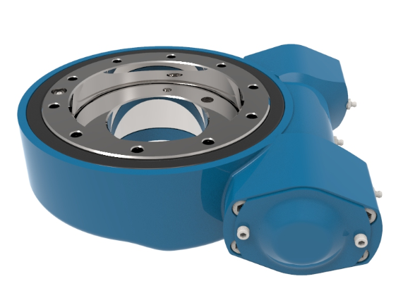
A slew drive, also known as a slewing drive, is a rotational drive component that provides controlled, continuous, and precise rotation about a single axis. It is fundamentally a complete system packaged into a compact housing. At its core, it consists of three primary elements:
Slewing Bearing (or Ring Gear): This is a large-diameter bearing, either a cross-roller bearing or a four-point contact ball bearing, capable of supporting combined loads. The bearing's outer or inner ring is typically machined with gear teeth, transforming it into a large-diameter gear.
Worm Screw (or Pinion): A precision-machined worm gear that meshes with the gear teeth on the bearing ring. The worm is connected to the input shaft, which is driven by a motor. The worm-and-wheel configuration is most common due to its inherent self-locking capability and high reduction ratio in a single stage.
Housing and Seals: A rugged, often cast housing encloses the entire assembly, providing structural integrity, alignment for the components, and protection from contaminants. High-quality seals are integral to keeping lubricant in and dirt, dust, and moisture out, ensuring long service life even in harsh environments.
The principle of operation is elegantly simple. rotational power from an electric, hydraulic, or pneumatic motor is applied to the input shaft, which turns the worm. As the worm rotates, it drives the geared ring of the slewing bearing. Because the worm offers a very high reduction ratio (e.g., 10:1 to 300:1 or more), the output rotation of the bearing is significantly slower than the input but delivers a massive increase in output torque. This allows a relatively small motor to control the movement of a structure weighing several tons.
2. Key Characteristics of Slew Drives
Slew drives are defined by a set of distinct characteristics that make them superior to alternative drive systems in many applications:
Compact and Integrated Design: By combining a bearing, gearbox, and mounting surface into one unit, slew drives save immense space and reduce the complexity of the host machine's design. This integration leads to a lighter overall weight and a simpler bill of materials.
High Load Capacity: Their design allows them to handle a unique combination of loads simultaneously:
Axial Load (Fa): Loads parallel to the axis of rotation (e.g., a weight pressing down directly on the top of the drive).
Radial Load (Fr): Loads perpendicular to the axis of rotation (e.g., a force trying to push the drive over sideways).
Moment Load (M): Tilting or overturning loads (e.g., a load cantilevered far out from the center of rotation, creating a massive tipping force). A single slew drive can routinely handle moment loads exceeding 1,000 kNm.
High Reduction Ratios and Self-Locking: The worm gear configuration is renowned for its ability to achieve high reduction ratios in a compact space. Crucially, most worm gears are self-locking; meaning back-driving (the output forcing the input to rotate) is impossible beyond a very low efficiency threshold (typically when the lead angle is less than the friction angle). This provides inherent safety and braking, holding loads securely in position without the need for an external brake, even in the event of a power failure.
Precision and Stiffness: The large diameter of the ring gear provides a long lever arm for fine positional control. High-quality manufacturing results in low backlash (often less than 5 arc-minutes for precision models), enabling precise positioning crucial for applications like solar tracking or robotic welding.
Durability and Environmental Resistance: Manufactured from high-grade case-hardened steels (e.g., 42CrMo4) and featuring hardened gear teeth (often to 58-62 HRC), slew drives are built for longevity. They are typically rated for tens of thousands of operating hours. IP65 or IP67 sealing is standard, making them suitable for outdoor, marine, and corrosive environments.
Benefits of Using a Slew Drive
The adoption of a slew drive system offers a multitude of tangible benefits that directly impact machine performance, cost, and reliability.
1. Simplified Design and Engineering: For original equipment manufacturers (OEMs), integrating a slew drive drastically simplifies the engineering process. Instead of sourcing, designing mounting interfaces for, and validating a separate bearing, gearbox, motor, and seals, engineers can select a single, pre-engineered, and pre-validated unit. This significantly reduces design time, computational analysis, and prototyping costs.
2. Enhanced Reliability and Reduced Maintenance: As an integrated unit, the slew drive is lubricated for life in many cases, requiring minimal maintenance. The sealed environment protects the critical worm and gear teeth from wear. This contrasts with traditional open gear and pinion systems, which are exposed to the elements and require frequent cleaning, inspection, and re-lubrication. The mean time between failures (MTBF) for a well-selected slew drive can be over 50,000 hours.
3. Space and Weight Savings: The compact nature of slew drives is a major advantage in applications where space is at a premium, such as in mobile machinery or within the nacelles of wind turbines. The elimination of external support structures for components leads to a lighter overall machine weight, which can improve fuel efficiency in mobile applications or allow for larger payloads.
4. Improved Safety: The self-locking feature is a critical safety benefit. It acts as an automatic fail-safe brake. For example, in a crane boom or an aerial work platform, if hydraulic pressure is lost or the motor fails, the self-locking worm gear will prevent the load from dropping or the boom from falling, protecting both equipment and personnel.
5. High Power Density and Performance: Slew drives deliver exceptional torque output relative to their size and the input power required. A compact hydraulic motor turning at 2,000 RPM and delivering 50 Nm of torque can, through a 100:1 slew drive, generate an output torque of 5,000 Nm. This high power density enables the use of smaller, more efficient motors.
6. Cost-Effectiveness in the Long Term: While the initial purchase price of a high-quality slew drive may be higher than a collection of separate components, the Total Cost of Ownership (TCO) is often lower. Reduced maintenance costs, less downtime, longer service life, and simplified inventory (one part number instead of many) contribute to significant savings over the operational lifespan of the machinery.
Types of Slew Drives
Slew drives are categorized based on their internal gear configuration and the number of worm gears employed. The choice depends on the load requirements and operational needs.
1. Single Worm Slew Drive: This is the most common and cost-effective configuration. It features one worm screw engaging with the internal or external gear teeth of the slewing bearing. It is ideal for applications with high loads but where resistance to extreme moment loads or redundancy is not the primary concern. Examples include light-to-medium duty solar trackers, irrigation systems, and smaller cranes.
2. Dual Worm Slew Drive: This design incorporates two worm screws, typically mounted 180 degrees apart, that engage with the same gear ring. This configuration offers several key advantages:
Load Distribution: The load is shared between two worms, effectively doubling the drive's moment load capacity and torsional stiffness.
Redundancy: In critical applications, if one worm or its motor fails, the other can often maintain control of the load long enough for a safe shutdown, enhancing safety.
Backlash Adjustment: Over time, wear can introduce backlash. In a dual worm design, backlash can often be adjusted out by repositioning one of the worms, thereby extending the unit's service life. These are used in heavy-duty applications like offshore cranes, tunnel boring machines, and satellite communication antennas.
3. Helical Gear Slew Drive: Instead of a worm gear, these drives use a helical pinion gear meshing with a helical ring gear. The main advantage is higher efficiency (up to 97% per stage compared to 40-85% for worm gears) and the ability to be back-driven. This is essential for applications like wind turbine yaw and pitch systems, where the external forces from the wind must be able to back-drive the system for safety and control reasons. They are not self-locking and require an external brake.
4. Axial vs. Radial Configuration: This refers to the orientation of the worm shaft relative to the axis of rotation.
Axial: The worm shaft is parallel to the main axis of rotation. This is the most common design, offering a compact profile.
Radial (or Vertical): The worm shaft is perpendicular to the main axis. This design can be beneficial for certain mounting arrangements where motor placement is constrained.
5. Mounting Orientation: Slew drives can be configured for different mounting patterns:
Horizontal Mount (Axis Vertical): The most common orientation, used in cranes, excavators, and solar azimuth trackers.
Vertical Mount (Axis Horizontal): Used in applications like the pitch control of wind turbine blades or certain types of material handling arms.
Installation and Maintenance of Slew Drives
Proper installation and maintenance are paramount to achieving the designed service life and performance of a slew drive.
Installation:
Handling: Slew drives are precision components. They must be lifted using appropriate lifting points (e.g., threaded holes in the housing marked for lifting) to avoid distorting the housing or damaging seals.
Mounting Surface: The mounting surface on the host machine must be machined to a strict flatness and co-planarity tolerance (often specified to be within 0.1 mm per meter of diameter). A warped mounting surface will pre-load the bearing, leading to premature failure.
Fastening: Use high-strength bolts of the correct grade (e.g., Class 10.9 or 12.9). Bolts must be tightened in a star pattern to the manufacturer's specified torque values using a calibrated torque wrench. Undertightening can lead to bolt fatigue and failure; overtightening can distort the housing.
Alignment: The connected components (motor, drive shafts) must be properly aligned to avoid imposing unexpected radial loads on the input shaft, which can cause seal wear and bearing failure.
Lubrication: Before operation, confirm the drive is filled with the correct type and volume of grease or oil. Common greases include NLGI 2 lithium complex or synthetic greases with extreme pressure (EP) additives.
Maintenance:
Regular Inspection: Schedule visual inspections for oil leaks, seal damage, and corrosion.
Re-lubrication: While many are "lubricated for life," drives in severe service conditions (high temperature, continuous operation, dirty environments) require periodic re-lubrication. The old grease must be purged to prevent additive breakdown from contaminating the new grease. Intervals can range from 500 to 2,000 hours.
Backlash Check: Periodically check for increased rotational backlash. A significant increase indicates wear in the gear mesh. In dual worm designs, this can sometimes be adjusted.
Noise and Vibration: Unusual noise or vibration is a primary indicator of a problem, such as wear, pitting, or brinelling of the bearing races.
A well-executed preventative maintenance program can extend the life of a slew drive by 50% or more, providing a strong return on investment.
Slew Drive Cost Analysis
The cost of a slew drive is not a simple figure; it is a function of multiple variables, and a holistic analysis must consider both CapEx and OpEx.
Initial Cost (Capital Expenditure - CapEx) Drivers:
Size and Load Capacity: The diameter of the bearing and the size of the gear teeth are the primary cost drivers. A drive with a 500mm diameter and a 10,000 Nm moment capacity may cost between $2,000 and $5,000, while a massive 2,000mm diameter drive for a heavy-lift crane with a 500,000 Nm capacity can exceed $50,000.
Precision and Quality: The manufacturing tolerances (e.g., gear quality, bearing runout) significantly impact cost. A drive with <5 arc-min backlash for a radar system will cost substantially more than a >15 arc-min drive for a slow-moving mixer.
Materials and Treatment: The use of high-grade steels and specialized heat treatments (case hardening, tempering) adds cost but is essential for durability.
Customization: Standard off-the-shelf drives are most economical. Customizations like special seal materials, coating (e.g., zinc-nickel plating for corrosion resistance), input shaft configurations, or mounting holes can increase cost by 20-50%.
Origin and Brand: European and North American brands (e.g., Cone Drive, Rolls-Royce, Bosch Rexroth) command a premium due to established quality and engineering support. Asian-manufactured drives can offer lower initial costs.
Operational Cost (Operational Expenditure - OpEx) Considerations:
Maintenance Costs: A slew drive has near-zero maintenance costs compared to an open gear system, which requires regular labor for cleaning and greasing. The savings in labor and lubricants can be thousands of dollars per year per machine.
Downtime Costs: This is often the largest hidden cost. A failure in a critical piece of equipment like a port crane or a tunnel boring machine can cost tens of thousands of dollars per hour in lost productivity. The superior reliability of a high-quality slew drive directly mitigates this risk.
Energy Efficiency: While worm gears are less efficient, their self-locking feature eliminates the need for an energy-consuming holding brake. Helical gear drives, though more efficient, require a brake. The total energy consumption must be modeled for the specific application duty cycle.
Therefore, the decision should be based on a Total Cost of Ownership (TCO) analysis over a 5-10 year period. A higher initial investment in a robust, reliable slew drive almost always results in a lower TCO due to massively reduced downtime and maintenance.
Applications of Slew Drives
Slew drives are ubiquitous in industries that require controlled heavy-duty rotation.
Renewable Energy: This is a massive growth sector. In solar tracking, slew drives are the preferred mechanism for both azimuth (horizontal) and elevation (tilt) rotation of photovoltaic panels, optimizing energy capture. A large single-axis tracker project can use over 10,000 slew drives. In wind turbines, multiple large-capacity helical slew drives are used for yaw control (keeping the nacelle facing the wind) and pitch control (adjusting the angle of each blade for power regulation).
Construction and Cranes: Tower cranes, mobile cranes, and excavators use slew drives in their upper structure to provide 360-degree continuous rotation. Their compactness and high load capacity are essential here.
Industrial Machinery: Found in welding positioners to rotate heavy workpieces, rotary tables for precision machining, mixers and agitators in mining and chemical processing, and automated storage and retrieval systems (ASRS).
Defense and Aerospace: Used in radar and satellite communication antennas for precise and stable positioning, often in extreme weather conditions. They are also found in turret systems on military vehicles.
Material Handling: In port automation, slew drives power the automated stacking cranes that move shipping containers. They are also used in robotic arms for heavy payload manipulation.
Important Considerations for Slew Drive Selection and Use
Selecting the right slew drive requires a careful analysis of the application's requirements. The following table outlines the key parameters that must be defined.
| Consideration | Description | Impact of Incorrect Selection |
|---|---|---|
| Load Analysis | Precisely calculating the combined loads: Axial (Fa), Radial (Fr), and Moment (M). This is the most critical step. The load must be calculated in all relevant operational positions. | Catastrophic Failure. Under-sizing will lead to premature bearing raceway brinelling, gear tooth breakage, or housing fracture. |
| Duty Cycle | Defining the operational regime: continuous vs. intermittent operation, number of expected rotations per day, percentage of time under full load. | Overheating. A drive selected for intermittent duty used continuously may overheat due to inadequate heat dissipation, breaking down the lubricant and damaging components. |
| Rotation Speed & Accuracy | Required output speed (RPM) and positional accuracy (backlash requirement). | Poor Performance. Too slow a speed reduces productivity; too much backlash makes precise positioning impossible for tasks like welding or machining. |
| Environmental Conditions | Operating temperature range, presence of corrosive elements (seawater, chemicals), dust, dirt, and moisture. | Corrosion and Wear. Standard seals and coatings will fail in harsh environments, leading to contaminant ingress, lubricant wash-out, and rapid wear. |
| Mounting Configuration | How the drive will be oriented (horizontal or vertical axis) and integrated into the machine structure. | Installation Failure. The drive may not physically fit, or the mounting may not be structurally sound to react to the imposed loads. |
| Drive Type | Choosing between worm gear (self-locking) and helical gear (efficient, back-drivable). | Safety Hazard. Using a non-self-locking drive in a crane application would be dangerously unstable without an external brake. |
| Lubrication | Selecting the correct grease type based on temperature and duty cycle. | Increased Friction & Wear. Incorrect lubricant can lead to poor efficiency, high operating temperatures, and accelerated component wear. |
| Maintenance Access | Planning for future inspection and re-lubrication points. | High OpEx. If the drive is installed in an inaccessible location, routine maintenance becomes difficult or impossible, shortening its life. |
Frequently Asked Questions (FAQ) About Slew Drives
Q1: What is the main difference between a slew drive and a standard rotary actuator?
A: While both provide rotational output, a slew drive is designed for very high torque and high load capacity at low speeds, integrating a large-diameter bearing to support these loads directly. A standard rotary actuator is typically smaller, faster, and designed for lower loads, often requiring an external bearing to support the applied loads.
Q2: How long does a slew drive typically last?
A: The service life (L10 life) of a slew drive is typically calculated in hours and can vary enormously. A well-selected and maintained drive in a moderate application can have an L10 life of 30,000 to 60,000 hours. This means 90% of drives will exceed this life. In harsh conditions, life may be shorter, but proper maintenance is key to maximizing longevity.
Q3: Can a slew drive be repaired, or does it need to be replaced entirely?
A: Major components like the housing and the slewing bearing ring are generally not repairable in the field. However, wearable items like seals, the worm shaft, and in some designs, the worm wheel, can be replaced by the manufacturer or a certified repair center. It is often more cost-effective to exchange the entire unit for a remanufactured one.
Q4: Why is the worm gear configuration so common despite its lower efficiency?
A: The trade-off is worth it for many applications. The self-locking feature provides inherent safety and eliminates the cost and complexity of an external brake. Furthermore, the ability to achieve a very high reduction ratio in a single stage results in a incredibly compact and simple design. For applications where holding a load is critical, efficiency is a secondary concern.
Q5: How do I size a slew drive for my application?
A: Sizing is a complex engineering task that should be done in collaboration with the drive manufacturer. You will need to provide:
The maximum moment, axial, and radial loads.
The required output speed.
The duty cycle (operating time, frequency of rotation).
Environmental conditions.
Any special requirements (backlash, certification standards).
Manufacturers provide selection software and engineering support to help calculate the required drive size and model based on these inputs.