How to Correctly Grease a Slew Drive
What is a Slew Drive
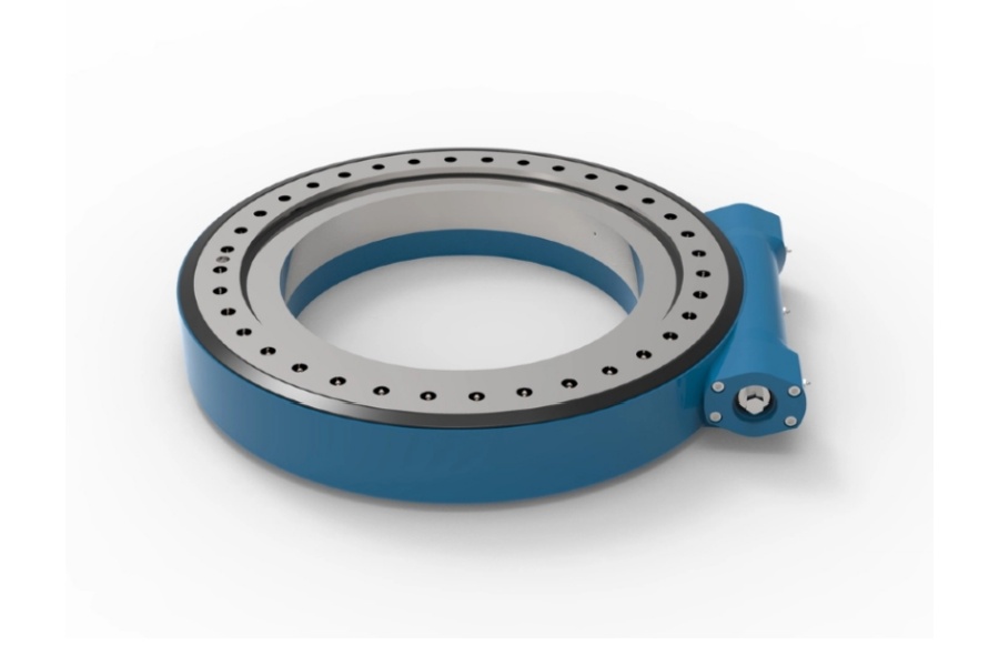
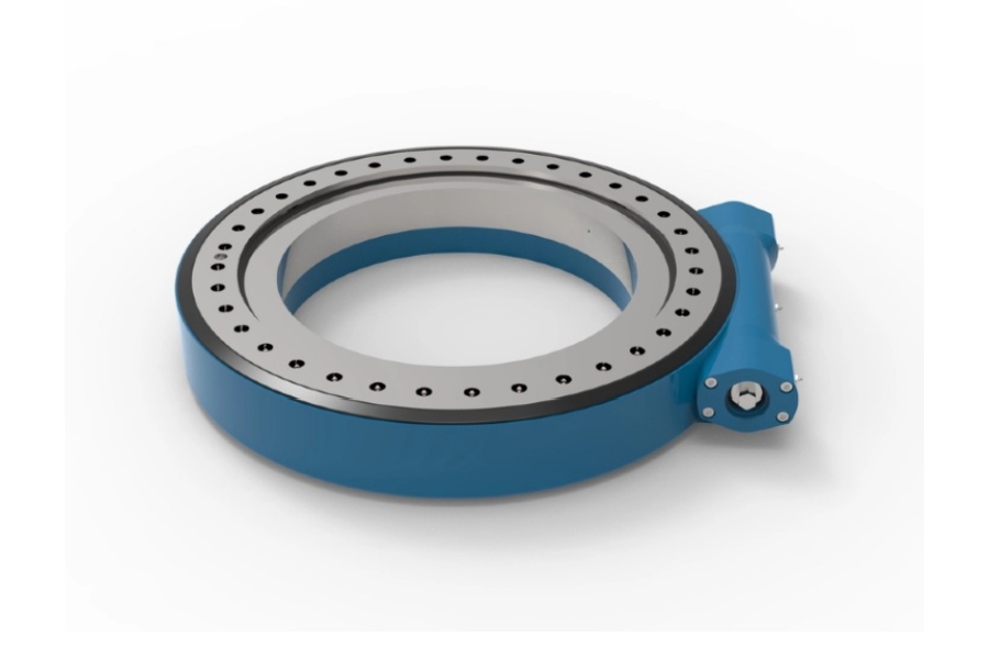
A slew drive, also known as a slewing drive, is a highly integrated rotational actuator fundamental to modern heavy-duty machinery. It is a compact and powerful assembly that combines a slewing bearing, a worm gear reduction, a housing, and frequently integral sealing and mounting features. The core of its function lies in the principle of the worm drive mechanism, where a worm screw meshes with a gear ring (either external or internal) that is integral to the bearing race. This configuration provides a substantial single-stage gear reduction, translating the high-speed, low-torque input from an electric or hydraulic motor into low-speed, high-torque rotational output. This allows relatively small motors to generate immense force to rotate extremely heavy loads. Crucially, the worm gear design often offers a self-locking feature, meaning the drive cannot be back-driven by the load, thus holding position securely without an external brake. Slew drives are engineered to support complex combinations of axial, radial, and moment loads simultaneously, making them the preferred solution for applications requiring robust, precise, and reliable rotation in a single compact unit. Their design simplifies engineering and installation for original equipment manufacturers (OEMs) across a vast array of industries.

How to Correctly Grease a Slew Drive
Proper lubrication is the single most critical maintenance activity for ensuring the longevity and reliable performance of a slew drive. Inadequate or incorrect greasing leads to increased friction, wear, premature failure of gear teeth and bearing races, and ultimately, catastrophic system breakdown. The following steps outline a meticulous procedure for correctly adding lubricant. The first and most crucial step is always to consult the manufacturer's specific manual for the particular slew drive model in use. This manual will provide authoritative information on the approved grease type, the exact lubrication intervals, the required volume or weight of grease, and the location of all grease fittings. Never assume that a general-purpose grease is suitable, as incompatible lubricants can cause seal degradation and component failure.
Before starting any maintenance, ensure the machinery is powered down and locked out according to safety protocols to prevent accidental activation. Visually inspect the slew drive for any signs of damage, particularly to the seals. Lubricating a unit with compromised seals will be ineffective and may force contaminants into the internal raceway, causing abrasive wear. Clean the area around the grease fittings (zerks) and the relief plugs thoroughly. Any dirt or debris present on these surfaces can be introduced into the lubrication circuit during the greasing process, acting as an abrasive and damaging the internal components. It is often recommended to gently exercise the slew drive through a partial rotation before greasing to loosen any old grease and contaminants, making them easier to purge.
Remove the relief plug or vent plug, which is typically located opposite the grease fitting or at the highest point on the housing. This is a non-negotiable step; failing to remove a relief plug will prevent the old, degraded grease from being purged and will risk over-pressurizing the housing, which can blow out seals and cause irreparable damage. Connect a clean, calibrated grease gun loaded with the manufacturer-specified grease to the grease fitting. Apply the grease slowly and steadily. The goal is to displace the old grease, not to generate extreme internal pressure. Observe the grease exiting the relief port. Continue pumping until fresh, clean grease of the same color as the new grease being injected emerges from the relief hole. This indicates that the old grease has been completely purged from the cavity.
Once fresh grease appears, immediately stop applying grease. Do not over-lubricate. Overfilling the internal cavity can lead to overheating due to churning and excessive pressure that compromises seals. Carefully remove the grease gun and clean any excess grease from the fitting. Reinstall the relief plug securely before wiping away any purged grease from the exterior of the unit and the surrounding structure. This final cleanup is important for both preventing a slip hazard and allowing for easier visual inspection during the next maintenance cycle. Record the date of lubrication, the number of hours on the machine, the type and amount of grease used, and any observations about the condition of the purged grease (e.g., presence of metal particles or water). This log is invaluable for tracking the drive's health and optimizing maintenance schedules. For drives in severe service conditions—such as continuous operation, extreme temperatures, or exposure to water and contaminants—the lubrication interval must be significantly shortened from the standard recommendations.
Characteristics of Slew Drives
Slew drives are defined by a unique set of engineering characteristics that make them indispensable in heavy-duty applications. Their most prominent feature is their ability to handle complex combination loads. A single, compact unit is designed to simultaneously support substantial axial forces (parallel to the axis of rotation), radial forces (perpendicular to the axis), and overturning moments (tilting forces). This multifunctional capability eliminates the need for additional custom-built support structures, simplifying design and saving space. The integrated worm gear mechanism provides a very high reduction ratio in a single stage, resulting in exceptionally high output torque. This allows for the use of smaller, more economical motors while still achieving the powerful rotational force required to move massive loads.
A critical characteristic stemming from the worm gear design is its inherent self-locking capability. For worm gears with a low lead angle, the friction within the gear set prevents the output from back-driving the input. This feature acts as a built-in brake, holding loads securely in position without the need for an external braking system, which is vital for safety in applications like cranes and elevators. Furthermore, slew drives offer excellent precision and controllability. The gear reduction allows for smooth and accurate positioning, which is essential in applications like solar tracking, radar antenna alignment, and robotic automation.
Their integrated and modular nature is another key characteristic. By combining the bearing, gearbox, seals, and often motor mounts into one pre-assembled and tested unit, slew drives drastically reduce engineering complexity and assembly time for OEMs. This integration also enhances the overall structural rigidity and torsional stiffness of the system, minimizing deflection under load and ensuring precise and repeatable movement. Finally, modern slew drives are built for durability and longevity. They utilize high-quality, hardened gear materials, advanced sealing systems to exclude contaminants, and are designed for either lifelong lubrication or easy maintenance access, ensuring reliability in the most demanding environments.
Applications of Slew Drives
The robust and versatile nature of slew drives has led to their widespread adoption across a diverse spectrum of industries where controlled rotation under heavy load is required. A dominant and growing application is in the renewable energy sector. In solar power generation, slew drives are the fundamental actuator in single-axis and dual-axis solar trackers. They precisely and slowly rotate massive arrays of photovoltaic panels to follow the sun's trajectory across the sky, increasing energy capture by up to 25-30% compared to fixed systems. Their self-locking capability is crucial here to prevent the panels from being moved out of position by wind loads.
Similarly, in the wind power industry, slew drives are critical components in both the yaw and pitch systems of wind turbines. The yaw system employs multiple large slew drives to rotate the entire nacelle to keep the rotor blades facing directly into the wind. The pitch control systems, located in the rotor hub, use smaller slew drives to individually adjust the angle of each blade to optimize power generation and manage structural loads during high winds. The construction and heavy equipment industry is another major sector reliant on slew drives. They provide the 360-degree rotation for excavator upper structures, the slewing motion for mobile crane booms, and the precise positioning for concrete pump booms and access platforms. Their compact design and high load capacity make them ideal for space-constrained mobile machinery.
Other significant applications include robotics and industrial automation, where they provide the heavy-duty rotational axes for robotic welders, palletizers, and assembly machines requiring precise positioning. The aerospace and defense sectors utilize them in radar and satellite communication antenna positioning systems, where they must deliver unwavering accuracy and reliability under harsh conditions. They are also found on deck cranes and winches on ships and vessels, in medical imaging equipment like CT and MRI scanners for patient positioning, and in the entertainment industry for rotating stages and heavy lighting rigs.
Factors Influencing Slew Drive Price
The cost of a slew drive is highly variable and is determined by a complex interplay of technical specifications, performance requirements, and commercial factors. The most fundamental cost driver is the physical size and load capacity of the unit. Larger drives with bigger bearing diameters and gear modules require significantly more raw material and involve more extensive machining and heat treatment, making a drive rated for 100-ton loads vastly more expensive than one for a light-duty application. The required precision and performance metrics also directly impact price. A unit engineered for ultra-precise, near-zero-backlash operation in a satellite antenna demands tighter manufacturing tolerances, higher-grade components (like ceramic balls), and more involved quality control than a drive for a construction excavator.
The choice of materials and corrosion protection specifications is a major contributor to the final cost. A standard carbon steel drive with a basic paint finish is the most economical option. However, specifying advanced protection like hot-dip galvanization, a proprietary Geomet® coating, or constructing the entire unit from stainless steel (e.g., 316 grade) adds a substantial premium. The integrated features and level of customization are highly variable cost factors. A standard, off-the-shelf unit is cheapest. Customizations such as special mounting flanges, integrated high-resolution encoders for position feedback, specific motor mounts, or special seals for chemical resistance require additional engineering and manufacturing effort, increasing the price.
Order quantity plays a crucial role due to economies of scale. A large-volume order for an OEM project allows the manufacturer to amortize fixed costs (like tooling and setup) over many units, drastically reducing the price per drive. Conversely, a one-off purchase for a replacement or a prototype will be comparatively expensive. Finally, external market dynamics, including fluctuations in raw material costs (e.g., steel prices) and global supply chain conditions, can influence the base price of components and finished goods.
Slew Drive Supplier
For engineers and procurement specialists seeking a reliable source for high-performance slew drives, LYRADRIVE stands as a trusted manufacturer and solutions provider. The company has built a strong reputation for engineering excellence, manufacturing precision, and a commitment to product durability. LYRADRIVE offers a comprehensive portfolio of standard and fully customized slew drive solutions designed to meet the rigorous demands of diverse industries, including renewable energy, construction, material handling, and industrial automation. A core strength of LYRADRIVE is its collaborative approach, working closely with clients to develop drive systems that perfectly integrate into specific applications, optimizing for load, speed, environmental conditions, and spatial constraints. Their technical support team provides expert guidance from the initial concept phase through to installation and maintenance, ensuring optimal performance and longevity. Furthermore, LYRADRIVE emphasizes rigorous quality control, utilizing high-grade materials and advanced manufacturing techniques to ensure every unit delivers exceptional reliability in the field.


